Table 2-8. Voltage and Percent Error For Various
Time Constants
/Time* 1 VM / % Error
7 IO.632 Es / 36
%
A. CIRCUIT
h?
0.632 ES
kL
RSCIN
6. EXPONENTIAL RESPONSE
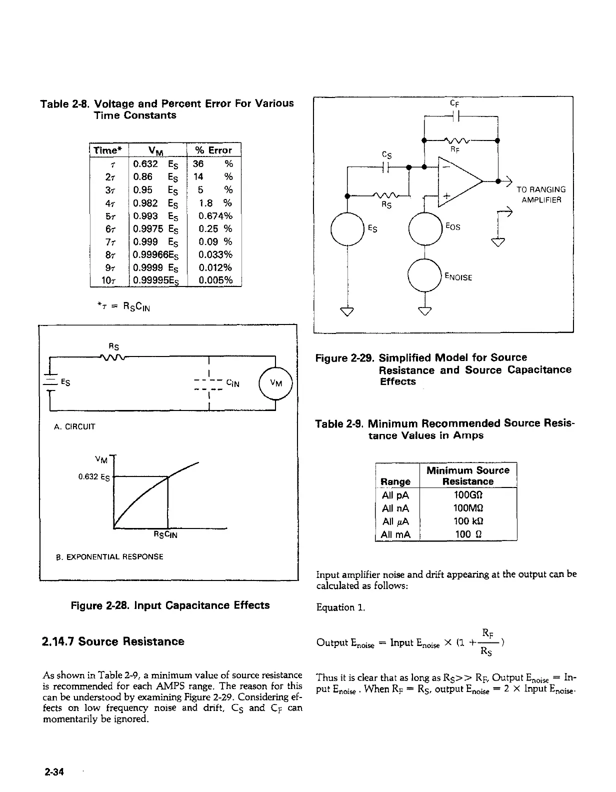
Input amplifier noise and drift appearing at the output can be
calculated as follows:
Figure 2-28. Input Capacitance Effects
Equation 1.
2.14.7 Source Resistance
Figure 2-29. Simplified Model for Source
Resistance and Source Capacitance
Effects
Table 2-9. Minimum Recommended Source Resis-
tance Values in Amps
Minimum Source
Range I
All pA 1
Resistance
lOOGil
1OOMQ
100 kQ
All mA
100 n
Output Enoise
RF
= Input En+ X (1 +-)
Rs
As shown in Table 2-9, a minimum value of source resistance
is recommended for each AMPS range. The reason for this
Thus it is clear that as long as Rs>> RF, Output E,,ise = In-
can be understood by examining Figure 2-29. Considering ef-
put En,,ire. When RF = Rs, output Enoh = 2 X Input Enoie.
fects on low frequency noise and drift, Cs and CF can
momentarily be ignored.
2-34
 Loading...


