CAUTION
Do not exceed 30V between the METER
COMPLETE ccmmcn (outer ring) and
chassis ground or instrument damage may
OCCW.
2. Select the desired function, range, trigger mode, and other
operating parameters, as desired.
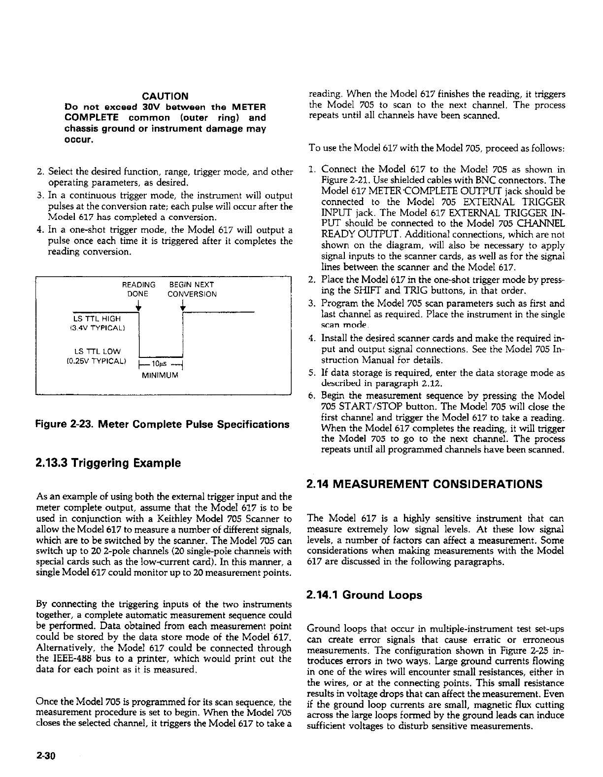
3. In a continuous trigger mode, the instrument will output
pulses at the conversion rate; each pulse will occur after the
Model 617 has completed a conversion.
4. In a one-shot trigger mode, the Model 617 will output a
pulse once each time it is triggered after it completes the
reading conversion.
Figure 2-23. Meter Complete Pulse Specifications
reading. When the Model 617 finishes the reading, it triggers
the Model 705 to scan to the next channel. The process
repeats until all channels have been scanned.
To use the Model 617 with the Model 705, proceed as follows:
1. Connect the Model 617 to the Model 705 as shown in
Figure Z-21. Use shielded cables with BNC connectors. The
Model 617 METERCOMPLETE OUTPUT jack should be
connected to the Model 705 EXTERNAL TRIGGER
INPUT jack. The Model 617 EXTERNAL TRIGGER IN-
PUT should be connected to the Model 705 CHANNEL
READY OUTPLIT Additional connections, which are not
shown on the diagram, will also be necessary to apply
signal inputs to the scanner cards, as well as for the signal
lines between the scanner and the Model 617.
2. Place the Model 617 in the one-shot trigger mode by press-
ing the SHIFT and TRIG buttons, in that order.
3. Program the Model 705 scan parameters such as first and
last channel as required. Place the instrument in the single
scan mode.
4. Install the desired scanner cards and make the required in-
put and output signal connections. See the Model 705 In-
struction Manual for details.
5. If data storage is required, enter the data storage mode as
described in paragraph 2.12.
6. Begin the measurement sequence by pressing the Model
705 START/STOP button. The Model 705 will close the
first channel and trigger the Model 617 to take a reading.
When the Model 617 completes the reading, it will trigger
the Model 705 to go to the next channel. The process
repeats until all programmed channels have been scanned.
2.13.3 Triggering Example
2.14 MEASUREMENT CONSIDERATIONS
As an example of using both the external trigger input and the
meter complete output, assume that the Model 617 is to be
used in conjunction with a Keithley Model 705 Scanner to
allow the Model 617 to measure a number of different signals,
which are to be switched by the scanner. The Model 705 can
switch up to 20 2-pole channels (20 single-pole channels with
special cards such as the low-current card). In this manner, a
single Model 617 could monitor up to 20 measurement points.
By connecting the triggering inputs of the two instruments
together, a complete automatic measurement sequence could
be performed. Data obtained from each measurement point
could be stored by the data store mode of the Model.617.
Alternatively, the Model 617 could be connected through
the IEEE-488 bus to a printer, which would print out the
data for each point as it is measured.
Once the Model 705 is programmed for its scan sequence, the
measurement procedure is set to begin. When the Model 705
closes the selected channel, it triggers the Model 617 to take a
The Model 617 is a highly sensitive instrument that can
measure extremely low signal levels. At these low signal
levels, a number of factors can affect a measurement. Some
considerations when making measurements with the Model
617 are discussed in the following paragraphs.
2.14.1 Ground Loops
Ground loops that occur in multiple-instrument test set-ups
can create error signals that cause erratic or erroneous
measurements. The configuration shown in Figure 2-25 in-
troduces errors in two ways. Large ground currents flowing
in one of the wires will encounter small resistances, either in
the wires, or at the connecting points. This small resistance
results in voltage drops that can affect the measurement. Even
if the ground loop currents are small, magnetic flux cutting
across the large loops formed by the ground leads can induce
sufficient voltages to disturb sensitive measurements.
Z-30
 Loading...


