The gain of the ranging amplifier is determined by the follow-
ing formula:
-RF
Av=-
R128
(Note that RF = R142 in parallel with R143, R145 or R146,
depending on which is selected).
For example, for X10 gain, the selected feedback resistor RF if
142, yielding a gain of:
-2MR
Av =
-= -10
2oOkQ
A = x10, x1. x0.1 OR x0.01
Figure 6-11. Simplified Schematic of Ranging
Amplifier
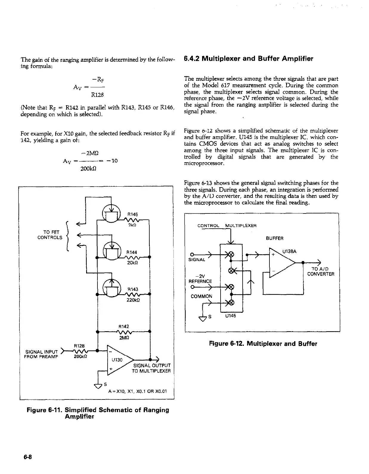
6.4.2 Multiplexer and Buffer Amplifier
The multiplexer selects among the three signals that are part
of the Model 617 measurement cycle. During the cormnon
phase, the multiplexer selects signal common. During the
reference phase, the -2V reference voltage is selected, while
the signal from the ranging amplifier is selected during the
signal phase.
Figure 6-12 shows a simplified schematic of the multiplexer
and buffer amplifier. U145 is the multiplexer IC. which con-
tains CMOS devices that act as analog switches to select
among the three input signals. The multiplexer IC is con-
trolled by digital signals that are generated by the
microprocessor.
Figure 6-13 shows the general signal switching phases for the
three signals. During each phase, an integration is performed
by the A/D converter, and the resulting data is then used by
the microprocessor to calculate the final reading.
CONTROL MULTIPLEXER
I
\L.
BUFFER
ID ID
RTER RTER
Figure 6-12. Multiplexer and Buffer
 Loading...


