For example, assume that the applied voltage is 1OOV. and the
measured current is 1pA. The resistance is calculated as
follows:
V
100
R =-=_=
10140
I
IPA
Since the user has fine control over the internal voltage source
(-102.35V to +102.4V in 5OmV steps), the resistance at a
given applied voltage can be easily determined. Such control
can give rise to voltage coefficient studies, as described later
in this section.
In addition to the measurement of insulation resistances, this
basic method can be used to measure unwanted leakage resis-
tances. For example, leakage resistance between PC board
traces and connectors can be made with either of the two
methods above, depending on the resistance values involved.
4.3 HIGH IMPEDANCE VOLTMETER
The input resistance of the Model 617 in the volts mode is
greater than ZOOTQ. Because of this high value, the Model 617
can be used to make voltage measurements in high impedance
circuits with a minimum of loading effects on the circuit.
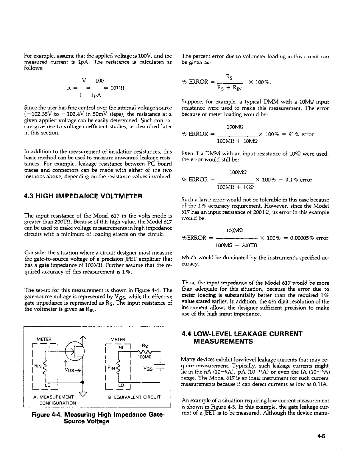
Consider the situation where a circuit designer must measure
the gate-to-source voltage of a precision JFET amplifier that
has a gate impedance of 1COMQ. Further assume that the re-
quired accuracy of this measurement is 1%
The set-up for this measurement is shown in Figure 4-4. The
gate-source voltage is represented by VGS, while the effective
gate impedance is represented as Rs. The input resistance of
the voltmeter is given as RN.
The percent error due to voltmeter loading in this circuit can
be given as:
% ERROR =
RS
x 100%.
Rs + RIN
Suppose, for example, a typical DMM with a 1OMR input
resistance were used to make this measurement. The error
because of meter loading would be:
1OOMQ
% ERROR =
x 100% = 91% elm2
1OOMR + lOMQ
Even if a DMM with an input resistance of 1OW were used,
the error would still be:
1OOMQ
% ERROR = x 100% = 9.1% error
lC0MQ + 1GO
Such a large error would not be tolerable in this case because
of the 1% accuracy requirement. However, since the Model
617 has an input resistance of 200TR. its error in this example
would be:
lWM0
%ERROR = x 100% = O.oooo5% error
1OOMQ + 2OOTQ
which would be dominated by the instrument’s specified ac-
curacy.
Thus, the input impedance of the Model 617 would be more
than adequate for this situation, because the error due to
meter loading is substantially better than the required 1%
value stated earlier. In addition, the 4~ digit resolution of the
instrument allows the designer sufficient precision to make
use of the high input impedance.
A. MEASUREMENT
v
B. EWIVALENT CIRCUIT
CONFIGURATION
Figure 4-4. Measuring High Impedance Gate-
Source Voltage
4.4 LOW-LEVEL LEAKAGE CURRENT
MEASUREMENTS
Many devices exhibit low-level leakage currents that may re-
quire measurement. Typically, such leakage currents might
lie in the nA (lo-9A), pA (lo-“A) or even the fA (lO-lsA)
range. The Model 617 is an ideal instrument for such current
measurements because it can detect currents as low as O.lfA.
An example of a situation requiring low current measurement
is shown in Figure 4-5. In this example, the gate leakage cur-
rent of a JFET is to be measured. Although the device manu-
4-5
 Loading...


