Minimum/Maximum Operation:
Minimum/Maximum operation is essentially separate from
data store except for the fact that both are enabled or disabled
by the ON/OFF button. Thus, the minimum and maximum
data points are continuously updated with each triggered
conversion as long as the ON/OFF LED is on. Note that only
range, not function, is indicated when reading maximum and
minimum values. Maximum and minimum values can be ob-
tained during the recall process, as indicated in step 4 above.
2.13 EXTERNAL TRIGGERING
The Model 617 has two external BNC connectors on the rear
panel associated with instrument triggering. The EXTERNAL
TRIGGER INPUT allows the instrument to be triggered by
other devices, while METER COMPLETE OUTPUT allows
the instrument to trigger other devices.
2.13.1 External Trigger
The Model 617 may be triggered on a continuous or one-shot
basis. For each of these modes, the trigger stimulus will de-
pend on the selected trigger mode, which is further described
in paragraph 3.10. In a continuous trigger mode, the instru-
ment takes a continuous series of readings. A trigger stimulus
in continuous triggers a new reading. In a one-shot mode,
only a single reading is taken each time the instrument is trig-
gered
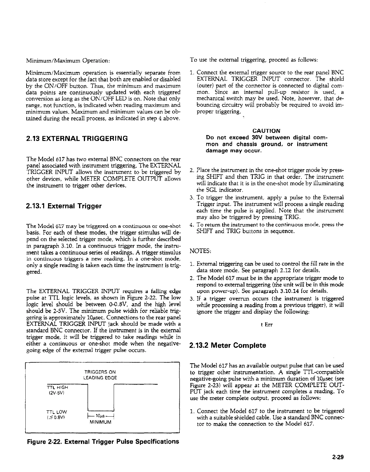
The EXTERNAL TRIGGER INPUT requires a falling edge
pulse at ‘ITL logic levels, as shown in Figure 2-22. The low
logic level should be between O-O.&‘, and the high level
should be 2-5V. The minimum pulse width for reliable trig-
gering is approximately lO+ec. Connections to the rear panel
EXTERNAL TRIGGER INPUT jack should be made with a
standard BNC connector. If the instrument is in the external
trigger mode, it will be triggered to take readings while in
either a continuous or one-shot mode when the negative-
going edge of the external trigger pulse occurs.
Figure 2-22. External Trigger Pulse Specifications
To use the external triggering, proceed as follows:
1. Connect the external trigger source to the rear panel BNC
EXTERNAL TRIGGER INPUT connector. The shield
(outer) part of the connector is connected to digital com-
mon. Since an internal pull-up resistor is used, a
mechanical switch may be used. Note, however, that de-
bouncing circuitry will probably be required to avoid im-
proper triggering.
CAUTION
Do not exceed 30V between digital com-
mon and chassis ground, or instrument
damage may occur.
2. Place the instrument in the one-shot trigger mode by press-
ing SHIFT and then TRIG in that order. The instrument
will indicate that it is in the one-shot mode by illuminating
the SGL indicator.
3. To trigger the instrument, apply a pulse to the External
Trigger input. The instrument will process a single reading
each time the pulse is applied. Note that the instrument
may also be triggered by pressing TRIG.
4. To return the instrument to the continuous mode, press the
SHIFT and TRIG buttons in sequence.
NOTES:
1. External triggering can be used to control the fill rate in the
data store mode. See paragraph 2.12 for details.
2. The Model 617 must be in the appropriate trigger mode to
respond to external triggering (the unit will be in this mode
upon power-up). See paragraph 3.10.14 for details.
3. If a trigger overrun occurs (the instrument is triggered
while processing a reading from a previous trigger), it will
ignore the trigger and display the following:
t En
2.13.2 Meter Complete
The Model 617 has an available output pulse that can be used
to trigger other instrumentation. A single lTL-compatible
negative-going pulse with a minimum duration of 10~sec (see
Figure 2-23) will appear at the METER COMPLETE OUT-
PUT jack each time the instrument completes a reading. To
use the meter complete output, proceed as follows:
1. Connect the Model 617 to the instrument to be triggered
with a suitable shielded cable. Use a standard BNC connec-
tor to make the connection to the Model 617.
2-29
 Loading...


