Note that an IJNL command is generally sent before the LAG,
SDC sequence. This is usually done to remove all other
listeners from the bus so that the desired device responds to
the command.
Table 3-3. Typical Addressed Command Sequence
Data Bus
itep Command ATN State
ASCII Hex Decimal
1
UNL Set low ? 3F
63
2
LAG* stays low I 36
59
3
SDC stays low EOT 04
4
4
Returns high
“Assumes primary address=27.
3.6.2 Universal Command Sequence
Universal commands are sent by setting ATN low and then
placing the command byte on the data bus. ATN would then
remain low during the period the command is transmitted.
For example, if the LLO command were to be sent, both ATN
and LLO would be asserted simultaneously.
3.6.3 Device-Dependent Command Sequence
Device-dependent commands are transmitted with ATN
false. However, a device must be addressed to listen before
these commands are transmitted. Table 3-4 shows the byte se-
quence for a typical Model 617 command (FOX), which sets
the instrument for the volts mode of operation.
Table 34. Typical Device-Dependent Command
Sequence
-
teP
i-
2
3
4
5
-
Command
UNL
LAG”
Data
Data
Data
*Assumes primary address = 27.
3.7 HARDWARE CONSIDERATIONS
Before the Model 617 can be operated over the IEEE-466 bus,
it must first be connected to the bus with a suitable cable.
Also, the primary address must be programmed to the correct
value, as described in the following paragraphs.
3.7.1 Typical Cohtrolled Systems
System configurations are many and varied and will depend
on the application. To obtain as much versatility as possible,
the IEEE-488 bus was designed so that additional instrumen-
tation could be easily added. Because of this versatility,
system complexity can range from the very simple to ex-
tremely complex.
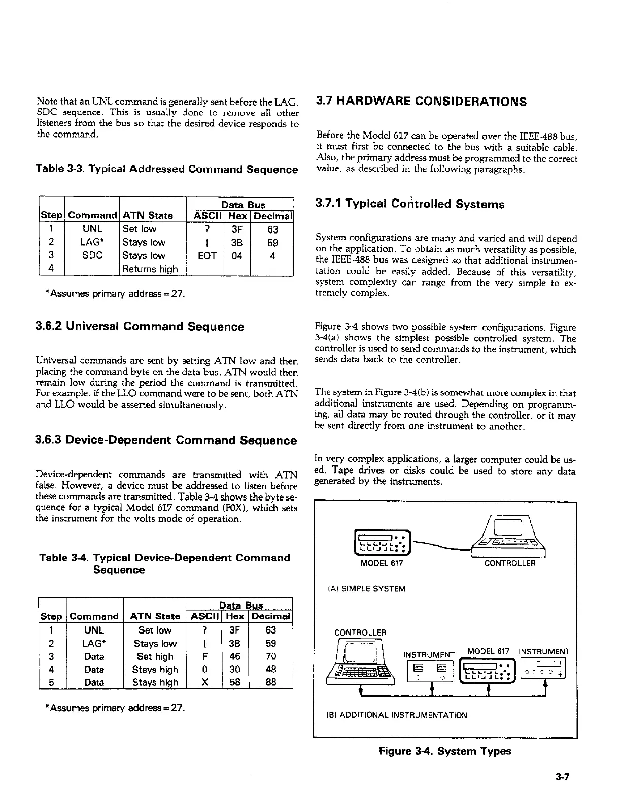
Figure 3-4 shows two possible system configurations. Figure
3-4(a) shows the simplest possible controlled system. The
controller is used to send commands to the instrument, which
sends data back to the controller.
The system in Figure 3-4(b) is somewhat more complex in that
additional instruments are used. Depending on programm-
ing, all data may be routed through the controller, or it may
be sent directly from one instrument to another.
In very complex applications, a larger computer could be us-
ed. Tape drives or disks could be used to store any data
generated by the instruments.
[~j~E$
MODEL 617 CONTROLLER
IA, SIMPLE SYSTEM
CONTROLLER
IS, ADDITIONAL INSTRUMENTATION
Figure 3-4. System Types
3-7
 Loading...


