EasyManua.ls Logo

Keithley 617 User Manual

Keithley 617
183 pages
To Next Page IconTo Next Page
To Previous Page IconTo Previous Page
Page #57 background imageLoading...
Page #57 background image
NRFD (Not Ready For Data&The acceptor controls the state
of NRFD. It is used to signal to the transmitting device to hold
off the byte transfer sequence.
NDAC (Not Data Accepted)-NDAC is also controlled by
the accepting device.
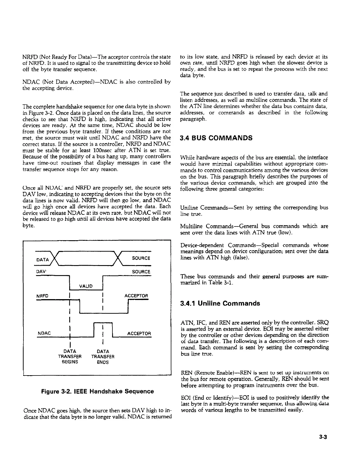
The complete handshake sequence for one data byte in shown
in Figure 3-Z. Once data is placed on the data lines, the source
checks to see that NRFD is high, indicating that all active
devices are ready. At the same time, NDAC should be low
from the previous byte transfer. If these conditions are not
met, the source must wait until NDAC and NRFD have the
correct status. If the source is a controller, NRFD and NDAC
must be stable for at least 1OOnsec after ATN is set true.
Because of the possibility of a bus hang up, many controllers
have time-out routines that display messages in case the
transfer sequence stops for any reason.
Once all NDAC and NRFD are properly set, the source sets
DAV low, indicating to accepting devices that the byte on the
data lines is now valid. NRFD will the” go low, and NDAC
will go high once all devices have accepted the data. Each
device will release NDAC at its own rate, but NDAC will not
be released to go high until all devices have accepted the data
byte
DA”’
SOURCE
VALID
NRFD
ACCEPTOR
I
I
I
I
I
NDAC
I
ACCEPTOR
,
I
I
DATA
DATA
TRANSFER
TRANSFER
BEGINS
ENDS
Figure 3-2. IEEE Handshake Sequence
Once NDAC goes high, the source then sets DAV high to in-
dicate that the data byte is no longer valid. NDAC is returned
to its low state, and NRFD is released by each device at its
own rate, until NRFD goes high when the slowest device is
ready, and the bus is set to repeat the preocess with the next
data byte.
The sequence just described is used to transfer data, talk and
listen addresses, as well as multiline commands. The state of
the ATN line determines whether the data bus contains data,
addresses, or commands as described in the following
paragraph.
3.4 BUS COMMANDS
While hardware aspects of the bus are essential, the interface
would have minimal capabilities without appropriate com-
mands to control communications among the various devices
on the bus. This paragraph briefly describes the purposes of
the various device commands, which are grouped into the
following three general categories:
Uniline Commands-Sent by setting the corresponding bus
line true.
Multiline Commands-General bus commands which are
sent over the data lines with ATN true (low).
Device-dependent Commands-Special commands whose
meanings depend on device configuration; sent over the data
lines with ATN high (false).
These bus commands and their general purposes are surn-
marized in Table 3-l.
3.4.1 Uniline Commands
ATN, IFC, and REN are asserted only by the controller. SRQ
is asserted by a” external device. EOI may be asserted either
by the controller or other devices depending on the direction
of data transfer. The following is a description of each com-
mand. Each command is sent by setting the corresponding
bus line true.
REN (Remote Enable)-REN is sent to set up instruments on
the bus for remote operation. Generally, REN should be sent
before attempting to program instruments over the bus.
EOI (End or Identify&E01 is used to positively identify the
last byte in a multi-byte transfer sequence, thus allowing data
words of various lengths to be transmitted easily.
53

Table of Contents

Other manuals for Keithley 617

Question and Answer IconNeed help?

Do you have a question about the Keithley 617 and is the answer not in the manual?

Keithley 617 Specifications

General IconGeneral
BrandKeithley
Model617
CategoryMeasuring Instruments
LanguageEnglish

Summary

Warranty Information

Warranty

Details the warranty terms and conditions for the product and specific components.

Specifications

Specifications

Details the electrical and performance specifications for the Model 617 electrometer.

Safety Precautions

Safety Precautions

Advises on essential safety measures to avoid injury and instrument damage during operation.

Section 1: General Information (Continued)

Unpacking and Getting Started

Details unpacking, inspection, and initial steps to operate the Model 617.

Section 2: Operation

2.2 Power Up Procedure

Details the steps for connecting power and turning on the instrument.

2.3 Power Up Self Test and Display Messages

Explains the self-test routine and potential display messages upon startup.

Section 2: Operation (Continued)

2.4 Front Panel Familiarization

Provides an overview of the Model 617's front panel layout, controls, and indicators.

2.7 Basic Measurement Techniques

Introduces fundamental procedures for making voltage, resistance, charge, and current measurements.

2.7.2 Input Connections

Details how to connect input signals to the rear panel INPUT connector.

2.7.4 Guarded Operation

Explains the concept and application of guarding to minimize leakage and improve measurements.

2.7.5 Making Current Measurements

Details the procedure for measuring low-level currents, including picoampere ranges.

2.7.6 Making Charge Measurements

Describes how to measure charge using the Model 617's coulombs ranges.

2.7.7 Resistance Measurements

Explains how to measure resistance using constant current and voltage methods.

2.8 Using The Voltage Source

Explains how to use the Model 617's built-in voltage source for V/I measurements.

2.10 Using External Feedback

Explains how to extend capabilities using external feedback networks.

2.11 Using Zero Correct and Baseline Suppression

Covers instrument offset cancellation and baseline value storage.

2.11.2 Using Suppression

Details how to store an offset value and subtract it from subsequent readings.

2.13 External Triggering

Explains how to trigger the instrument using external BNC connectors.

2.4.1 Controls

Describes the function and operation of each front panel control button.

2.5.3 Calibration

Introduces the digital calibration program for front panel or IEEE-488 bus use.

2.7.3 Making Voltage Measurements

Provides step-by-step instructions for measuring DC voltages with the Model 617.

2.8.1 Basic Operating Procedure

Guides on connecting and adjusting the voltage source output.

2.11.1 Zero Correct and Zero Check

Explains how to use Zero Correct and Zero Check to cancel internal offsets.

2.12 Data Storage

Describes the internal 100-point data store mode for logging readings.

2.13.1 External Trigger

Details continuous and one-shot triggering modes via the external trigger input.

2.14 Measurement Considerations

Discusses factors affecting measurements at low signal levels.

2.8.2 V/I Resistance Measurements

Describes how to measure high resistances using the voltage source and electrometer.

Section 3: IEEE-488 Programming

Section 3: IEEE-488 Programming (Continued)

3.4 Bus Commands

Covers device commands, grouped into uniline, multiline, and device-dependent categories.

3.7.2 Bus Connections

Details how to connect the Model 617 to the IEEE-488 bus using appropriate cables.

3.7.3 Primary Address Programming

Explains how to check and set the instrument's primary address for bus communication.

3.8 Software Considerations

Discusses software aspects for IEEE-488 controllers like HP-85 and IBM-PC.

3.9 General Bus Command Programming

Covers general bus commands like DCL, REN, IFC, LLO, GTL, SDC, GET, SPE, SPD.

3.10 Device-Dependent Command Programming

Details commands controlling modes like function, range, trigger, and data format.

3.10.2 Function (F)

Describes commands to select measurement functions like Volts, Amps, Ohms, Coulombs.

3.10.3 Range (R)

Explains commands for controlling instrument sensitivity and selecting measurement ranges.

3.10.4 Zero Correct and Zero Check (Z and C)

Details commands for canceling internal offsets and zeroing the instrument.

3.10.5 Baseline Suppression (N)

Explains commands to store an offset and subtract it from subsequent readings.

3.10.9 Voltage Source Value (V)

Details commands for programming the built-in voltage source output.

3.4.5 Device-Dependent Commands

Describes commands specific to device configuration, controlling functions like mode and range.

3.10.8 Data Store Mode

Explains how to use the data store for logging readings and setting intervals.

3.10.11 Calibration Value (A)

Describes commands for setting calibration values for ranges and functions.

Section 4: Applications

4.2 Insulation Resistance Measurements

Details how to measure high insulation resistances using constant current and voltage methods.

Section 4: Applications (Continued)

4.3 High Impedance Voltmeter

Explains using the Model 617 as a high-impedance voltmeter with minimal circuit loading.

4.4 Low-Level Leakage Current Measurements

Guides on measuring low-level currents like nanoamperes and picoamperes.

Section 5: Performance Verification

Section 5: Performance Verification (Continued)

5.5 Verification Procedures

Provides detailed procedures for verifying accuracy of volts, ohms, amps, and coulombs functions.

Section 7: Maintenance

Section 7: Maintenance (Continued)

7.4.5 Front Panel Calibration

Provides step-by-step instructions for calibrating from the front panel.

7.4.11 Amps Calibration

Provides calibration steps for the amps function across various ranges.

7.4.12 Coulombs Calibration

Details the procedure for calibrating the coulombs function.

7.4.14 Ohms Calibration

Provides calibration steps for the ohms function across various ranges.

7.4.15 Voltage Source Calibration

Details the procedure for calibrating the instrument's internal voltage source.

7.4 Calibration

Introduces digital calibration capabilities and recommendations.

7.4.6 IEEE-488 Bus Calibration

Details procedures for calibrating the instrument via the IEEE-488 bus using a computer.

7.4.8 Input Offset Adjustment

Describes steps to null any small offset in the input amplifier.

7.4.13 Volts Calibration

Outlines the calibration steps for the volts function across different ranges.

7.7 Troubleshooting

Offers guidance for diagnosing and resolving instrument problems.

7.4.9 Input Current Adjustment

Details procedures to null input current in the input stage for temperature compensation.

Related product manuals