EasyManua.ls Logo

Keithley 617 User Manual

Keithley 617
183 pages
To Next Page IconTo Next Page
To Previous Page IconTo Previous Page
Page #85 background imageLoading...
Page #85 background image
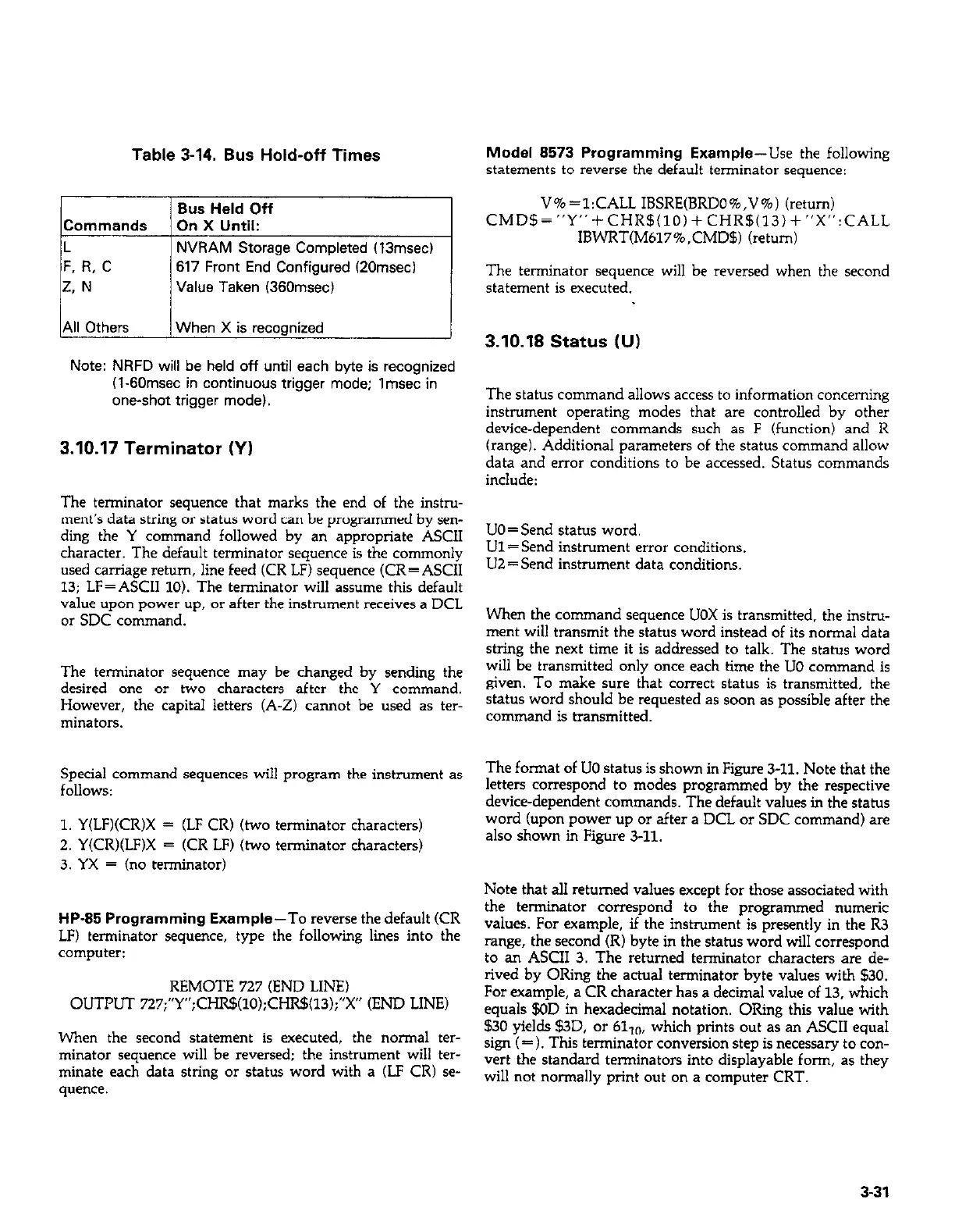
Table 3-14. Bus Hold-off Times
Model 8573 Programming Example-Use the following
statements to reverse the default terminator sequence:
Bus Held Off
V%=l:CALL IBSRE(BRDO%,V%) (return)
Commands On X Until:
CMD!§=“Y”+CHR$(lO)+CHR$(13)+“X”:CALL
L
NVRAM Storage Completed (13msec)
IBWRT(M617%,CMD$) (return)
F. R, C
617 Front End Configured (20msecl
2. N
Value Taken (36Omsec)
The terminator sequence will be reversed when the second
statement is executed.
All Others
When X is recognized
3.10.18 Status NJ)
Note: NRFD will be held off until each byte is recognized
(1.60msec in continuous trigger mode; Imsec in
one-shot trigger model.
The status command allows access to information concerning
instrument ooeratinz modes that are controlled bv other
device-dependent c&mands such as F (functionj’and R
3.10.17 Terminator (Y)
(range). Additional parameters of the status command allow
data and error conditions to be accessed. Status commands
include:
The terminator sequence that marks the end of the instru-
ment’s data string or status word can be programmed by sen-
ding the Y command followed by an appropriate ASCII
UO=Send status word.
character. The default terminator sequence is the commonly
Ul=Send instrument error conditions.
used carriage return, line feed (CR LF) sequence (CR=ASCII
UZ=Send instrument data conditions.
13: LF=ASCII 10). The terminator will assume this default
value upon power’up, or after the instrument receives a DCL
or SDC command.
When the command sequence UOX is transmitted. the instru-
ment will transmit the status word instead of its normal data
string the next time it is addressed to talk. The status word
The terminator sequence may be changed by sending the
will be transmitted only once each time the UO command is
desired one or two characters after the Y command.
given. To make sure that correct status is transmitted, the
However, the capital letters (A-Z) cannot be used as ter-
status word should be requested as soon as possible after the
minators.
command is transmitted.
Special command sequences will program the instrument as
The format of UO status is shown in Figure 3-11. Note that the
follows:
letters correspond to modes programmed by the respective
device-dependent commands. The default values in the status
1. Y(LF)(CR)X = (LF CR) (two terminator characters)
2. Y(CR)(LF)X = (CR LF) (two terminator characters)
word (upon power up or after a DCL or SDC command) are
also shown in Figure 3-11.
3. YX = (no terminator)
Note that al1 returned values except for those associated with
HP-85 Programming Example-To reverse the default (CR
the terminator correspond to ihe programmed numeric
LF) terminator sequence, type the following lines into the
values. For example, if the instrument is presently in the R3
computer:
range, the second (R) byte in the statLls word will correspond
to an ASCII 3. The returned terminator characters are de-
REMOTE 727 (END LINE)
rived by ORing the actual terminator byte values with $30.
OUTPUT 727;“Y”;CHR$(lO);CHR!§(l3);“X” (END LINE)
For example, a CR character has a decimal value of 13, which
equals $OD in hexadecimal notation. ORing this value with
When the second statement is executed, the normal ter-
$30 yields $3D, or 6110, which prints out as an ASCII equal
minator sequence will be reversed; the instrument will ter-
sign (= ). This terminator conversion step is necessary to con-
minate each data string or status word with a (LF CR) se-
vert the standard terminators into displayable form, as they
will not normally print out on a computer CRT.
quence.
3-31

Table of Contents

Other manuals for Keithley 617

Question and Answer IconNeed help?

Do you have a question about the Keithley 617 and is the answer not in the manual?

Keithley 617 Specifications

General IconGeneral
BrandKeithley
Model617
CategoryMeasuring Instruments
LanguageEnglish

Summary

Warranty Information

Warranty

Details the warranty terms and conditions for the product and specific components.

Specifications

Specifications

Details the electrical and performance specifications for the Model 617 electrometer.

Safety Precautions

Safety Precautions

Advises on essential safety measures to avoid injury and instrument damage during operation.

Section 1: General Information (Continued)

Unpacking and Getting Started

Details unpacking, inspection, and initial steps to operate the Model 617.

Section 2: Operation

2.2 Power Up Procedure

Details the steps for connecting power and turning on the instrument.

2.3 Power Up Self Test and Display Messages

Explains the self-test routine and potential display messages upon startup.

Section 2: Operation (Continued)

2.4 Front Panel Familiarization

Provides an overview of the Model 617's front panel layout, controls, and indicators.

2.7 Basic Measurement Techniques

Introduces fundamental procedures for making voltage, resistance, charge, and current measurements.

2.7.2 Input Connections

Details how to connect input signals to the rear panel INPUT connector.

2.7.4 Guarded Operation

Explains the concept and application of guarding to minimize leakage and improve measurements.

2.7.5 Making Current Measurements

Details the procedure for measuring low-level currents, including picoampere ranges.

2.7.6 Making Charge Measurements

Describes how to measure charge using the Model 617's coulombs ranges.

2.7.7 Resistance Measurements

Explains how to measure resistance using constant current and voltage methods.

2.8 Using The Voltage Source

Explains how to use the Model 617's built-in voltage source for V/I measurements.

2.10 Using External Feedback

Explains how to extend capabilities using external feedback networks.

2.11 Using Zero Correct and Baseline Suppression

Covers instrument offset cancellation and baseline value storage.

2.11.2 Using Suppression

Details how to store an offset value and subtract it from subsequent readings.

2.13 External Triggering

Explains how to trigger the instrument using external BNC connectors.

2.4.1 Controls

Describes the function and operation of each front panel control button.

2.5.3 Calibration

Introduces the digital calibration program for front panel or IEEE-488 bus use.

2.7.3 Making Voltage Measurements

Provides step-by-step instructions for measuring DC voltages with the Model 617.

2.8.1 Basic Operating Procedure

Guides on connecting and adjusting the voltage source output.

2.11.1 Zero Correct and Zero Check

Explains how to use Zero Correct and Zero Check to cancel internal offsets.

2.12 Data Storage

Describes the internal 100-point data store mode for logging readings.

2.13.1 External Trigger

Details continuous and one-shot triggering modes via the external trigger input.

2.14 Measurement Considerations

Discusses factors affecting measurements at low signal levels.

2.8.2 V/I Resistance Measurements

Describes how to measure high resistances using the voltage source and electrometer.

Section 3: IEEE-488 Programming

Section 3: IEEE-488 Programming (Continued)

3.4 Bus Commands

Covers device commands, grouped into uniline, multiline, and device-dependent categories.

3.7.2 Bus Connections

Details how to connect the Model 617 to the IEEE-488 bus using appropriate cables.

3.7.3 Primary Address Programming

Explains how to check and set the instrument's primary address for bus communication.

3.8 Software Considerations

Discusses software aspects for IEEE-488 controllers like HP-85 and IBM-PC.

3.9 General Bus Command Programming

Covers general bus commands like DCL, REN, IFC, LLO, GTL, SDC, GET, SPE, SPD.

3.10 Device-Dependent Command Programming

Details commands controlling modes like function, range, trigger, and data format.

3.10.2 Function (F)

Describes commands to select measurement functions like Volts, Amps, Ohms, Coulombs.

3.10.3 Range (R)

Explains commands for controlling instrument sensitivity and selecting measurement ranges.

3.10.4 Zero Correct and Zero Check (Z and C)

Details commands for canceling internal offsets and zeroing the instrument.

3.10.5 Baseline Suppression (N)

Explains commands to store an offset and subtract it from subsequent readings.

3.10.9 Voltage Source Value (V)

Details commands for programming the built-in voltage source output.

3.4.5 Device-Dependent Commands

Describes commands specific to device configuration, controlling functions like mode and range.

3.10.8 Data Store Mode

Explains how to use the data store for logging readings and setting intervals.

3.10.11 Calibration Value (A)

Describes commands for setting calibration values for ranges and functions.

Section 4: Applications

4.2 Insulation Resistance Measurements

Details how to measure high insulation resistances using constant current and voltage methods.

Section 4: Applications (Continued)

4.3 High Impedance Voltmeter

Explains using the Model 617 as a high-impedance voltmeter with minimal circuit loading.

4.4 Low-Level Leakage Current Measurements

Guides on measuring low-level currents like nanoamperes and picoamperes.

Section 5: Performance Verification

Section 5: Performance Verification (Continued)

5.5 Verification Procedures

Provides detailed procedures for verifying accuracy of volts, ohms, amps, and coulombs functions.

Section 7: Maintenance

Section 7: Maintenance (Continued)

7.4.5 Front Panel Calibration

Provides step-by-step instructions for calibrating from the front panel.

7.4.11 Amps Calibration

Provides calibration steps for the amps function across various ranges.

7.4.12 Coulombs Calibration

Details the procedure for calibrating the coulombs function.

7.4.14 Ohms Calibration

Provides calibration steps for the ohms function across various ranges.

7.4.15 Voltage Source Calibration

Details the procedure for calibrating the instrument's internal voltage source.

7.4 Calibration

Introduces digital calibration capabilities and recommendations.

7.4.6 IEEE-488 Bus Calibration

Details procedures for calibrating the instrument via the IEEE-488 bus using a computer.

7.4.8 Input Offset Adjustment

Describes steps to null any small offset in the input amplifier.

7.4.13 Volts Calibration

Outlines the calibration steps for the volts function across different ranges.

7.7 Troubleshooting

Offers guidance for diagnosing and resolving instrument problems.

7.4.9 Input Current Adjustment

Details procedures to null input current in the input stage for temperature compensation.

Related product manuals