3. Connect the DC calibrator and decade resistance box to
the instrument as shown in Figure 5-2.
4. With zero check still enabled, verify that the display reads
O.ooO ?I count. If not, enable zero correct.
5. Apply the correct input by setting the DC calibrator and
decade box to the values listed in Table 5-2.
6. Disable zero check. Check to see that the reading is within
the limits listed in the table.
8. Repeat the procedure for the 2oOnA-2mA ranges, as listed
in Table 5-2. Be sure to set both the decade box and DC
calibrator to the values listed.
9. Using the teraohmmeter, measure the actual value of the
1COMR resistor and record its value in the appropriate
space in the table.
NOTE
Do not touch the body of the resistor to avoid
contamination which could give erroneous
results.
10. Calculate the actual calibrator voltage by multiplying the
measured resistor value by the calibration current for that
range. For example, if the ac& resistance is 99MO, the
required calibrator voltage is V=(99 X 106) (19 X 10-q)
= 1.88lV. Write the calculated value in Table 5-2.
11. Set the calibrator voltage to the exact value obtained in
step 10.
12. Place the instrument on the 20nA range and enable zero
check. Verify that the display shows O.ooO rtl count. If
not, enable zero correct.
13. Mount the 1OOMQ resistor in the shielded fixture (con-
struction is covered in Figure 5-l) and connect the fixture
to the instrument, as shown in Figure 5-3.
NOTE
Disconnect floating sources when using this con-
figuration.
14. Disable zero check and verify that the reading is within
the limits given in Table 5-2. Enable zero check.
15. Repeat steps 9 through 14 for the 2nA-2pA ranges. For
each range, measure the actual resistor value and
calculate the calibrarion voltage using that value along
with the required calibration current.
5.5.3 Coulombs Verification
To confirm coulombs operation, proceed as follows:
1. Enable zero check and set the DC calibrator output to
QO.000.
2. Connect the 1OOOpF capacitor, the calibrator, and the
Model 617 together, as shown in Figure 5-4.
NOTE
Disconnect floating sources when using this con-
figuration.
3. Place the instrument in the coulombs mode and select the
2°C range. Enable zero correct.
4. Disable zero check, enable suppress, and set the DC
calibrator output to l.oooOV.
5. Verify that the display reads between 0.995 and 1.005nC.
6. Enable zero check and set the calibrator output to O.oooOV.
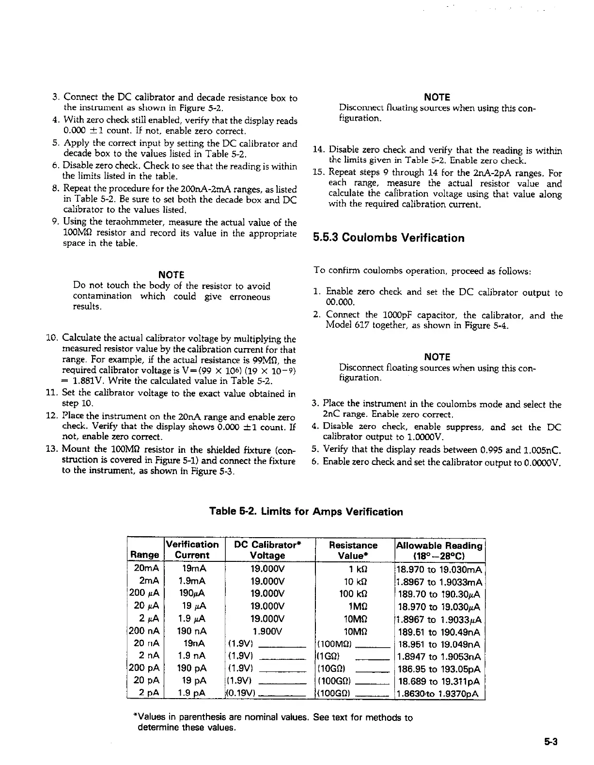
Table 52. Limits for Amps Verification
DC Calibrator* Resistance Allowable Readins
Voltage Value*
(W-28W
19.ooov
1 kCl
18.970 to 19.030mP
10 kfl 1.8967
to 1.9033mP ,
100 kQ 189.70
to 190.30rA
1MCl
18.970 to 19.030pA
lOM0
1.8967 to 1.9033@
10MQ
189.51 to 190.49nA
(100MQl 18.951 to 19.049nA
(1GW
- 1.8947
to 1.9053nA
IlOGR) __
186.95 to 193.05pA
(lOOGO) __
18.689 to 19.311pA
(100GW - 1.863O’to 1.9370pA
I
*Values in parenthesis are nominal values. See text for methods to
determine these values.
53
 Loading...


