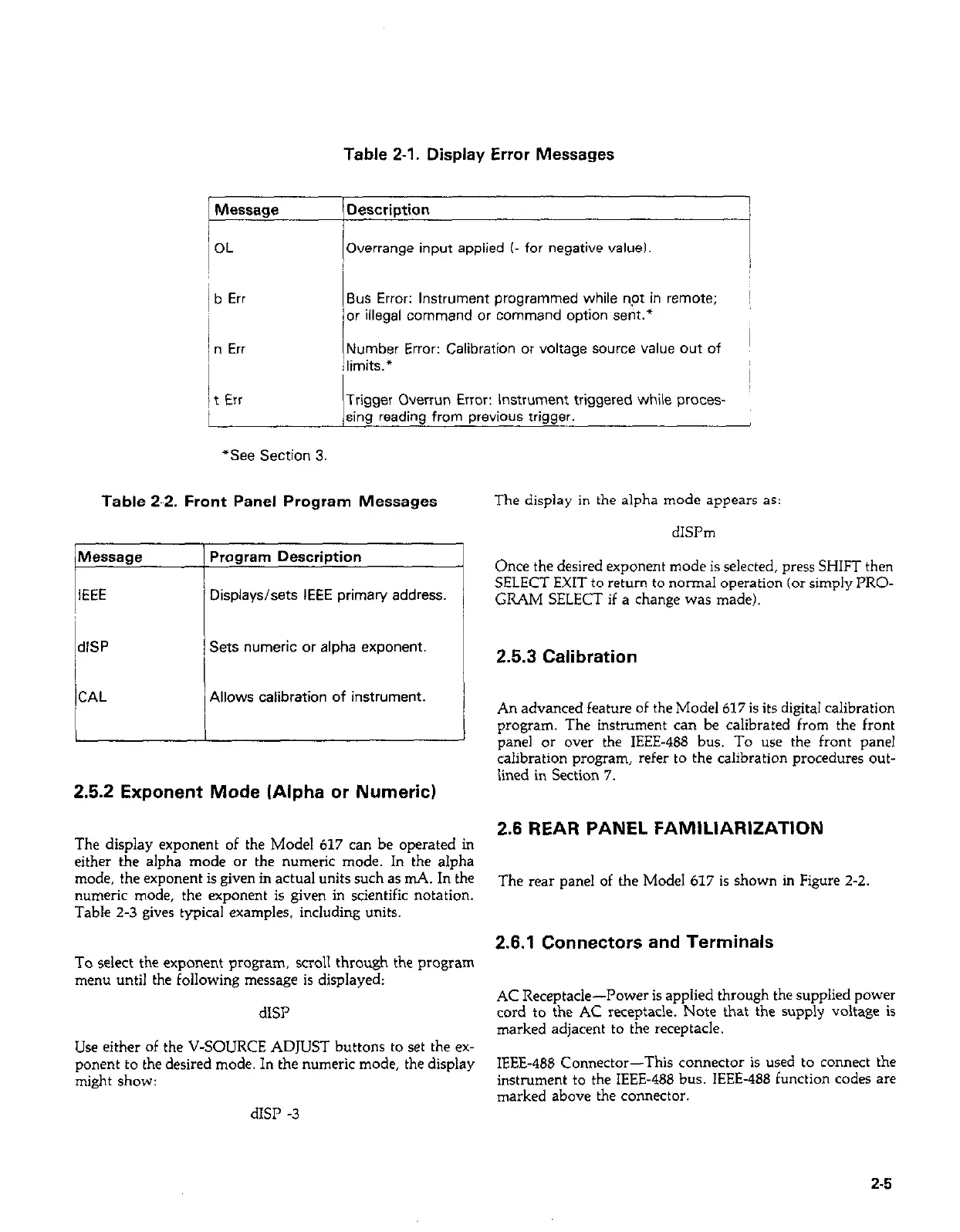
Table 2-1. Display Error Messages
Message
OL
b Err
Description
Overrange input applied (- for negative valueI.
Bus Error: Instrument programmed while npt in remote; ~
or illegal command or command option sent.*
n Err
‘t Err
(Number Error: Calibration or voltage source value out of
I
; limits.*
I
Trigger Overrun Error: Instrument triggered while proces-
sing reading from previous trigger.
“See Section 3.
Table 2-2. Front Panel Program Messages
The display in the alpha mode appears as:
IdlSP
CAL
Displays/sets IEEE primary address.
Sets numeric or alpha exponent.
Allows calibration of instrument.
2.5.2 Exponent Mode (Alpha or Numeric)
The display exponent of the Model 617 can be operated in
either the alpha mode or the numeric mode. In the alpha
mode, the exponent is given in actual units such as mA. In the
numeric mode, the exponent is given in scientific notation.
Table 2-3 gives typical examples. including units.
To select the exponent program, scroll through the program
menu until the following message is displayed:
dISI’
Use either of the V-SOURCE ADJUST buttons to set the ex-
ponent to the desired mode. In the numeric mode, the display
might show:
dISP -3
dISI’m
Once the desired exponent mode is selected, press SHIFT then
SELECT EXIT to return to normal operation (or simply PRO-
GRAM SELECT if a change was made).
2.5.3 Calibration
An advanced feature of the Model 617 is its digital calibration
program. The instrument can be calibrated from the front
panel or over the IEEE-488 bus. To use the front panel
calibration program, refer to the calibration procedures out-
iined in Section 7.
2.6 REAR PANEL FAMILIARIZATION
The rear panel of the Model 617 is shown in Figure 2-2.
2.6.1 Connectors and Terminals
AC Receptacle-Power is applied through the suppiied power
cord to the AC receptacle. Note that the supply voltage is
marked adjacent to the receptacle.
IEEE-488 Connector-This connector is used to connect the
instrument to the IEEE-488 bus. IEEE-488 function codes are
marked above the connector.
2-5
 Loading...


