Environmental Conditions
Calibration should be performed under laboratory condi-
tions having an ambient temperature of 23 &PC and a
relative humidity of less than 70%. With both the Models
617 and 263 on, allow them to warm up for one hour. Jf
either instrument has been subjected to exlwme tempera-
ture or humidity, allow at least one additional hour for the
instrument to stabilize before beginning the calibration
procedure.
NOTE
While rated accuracy of the Model 617 is achieved
after the two hour warm up period, input bias cur-
rent may require additional time to come to its op-
timum level. Allow two hours for input bias cur-
rent to settle to less than 1OfA and eight hours to
less than 5fA.
Calibration Sequence
Model 637 calibration must be performed in the order given
in the following paragraphs, with the exception of the
voltage source calibration, which can be done at any time.
The basic sequence is:
Manual Adjustments:
1. Input offset adjustment
2. Input current adjustment
3. Voltage source calibration adjustments
Digital Calibration (Front Panel or IEEE-488 Bus):
4. Amps calibration
5. Coulombs calibration
6. Volts calibration
7. Ohms calibration
The voltage source is calibrated third since this is a manual
adjustment. This allows the digital calibration procedures
to be grouped together.
In addition to the above sequence, the ranges for each
function must be calibrated in the order given. Note that
you should never calibrate a range using a suppress or a
zero correct value taken on a different range.
Manual Calibration Adjustments
After performing the following manual calibration ad-
justments, proceed to either front panel digital calibration
or IEEE-488 Bus Digital Calibration.
A. Input Offset Adjustment
Perform the following ‘steps to null out any small offset in
the input amplifier:
1. Disconnect all input signals from the Model 617.
2. Remove the two screws securing the top cover and
remove the cover from the instrument.
3. Select the amps function and place the instrument on
the 2pA range.
4. Enable zero check, but leave zero correct disabled.
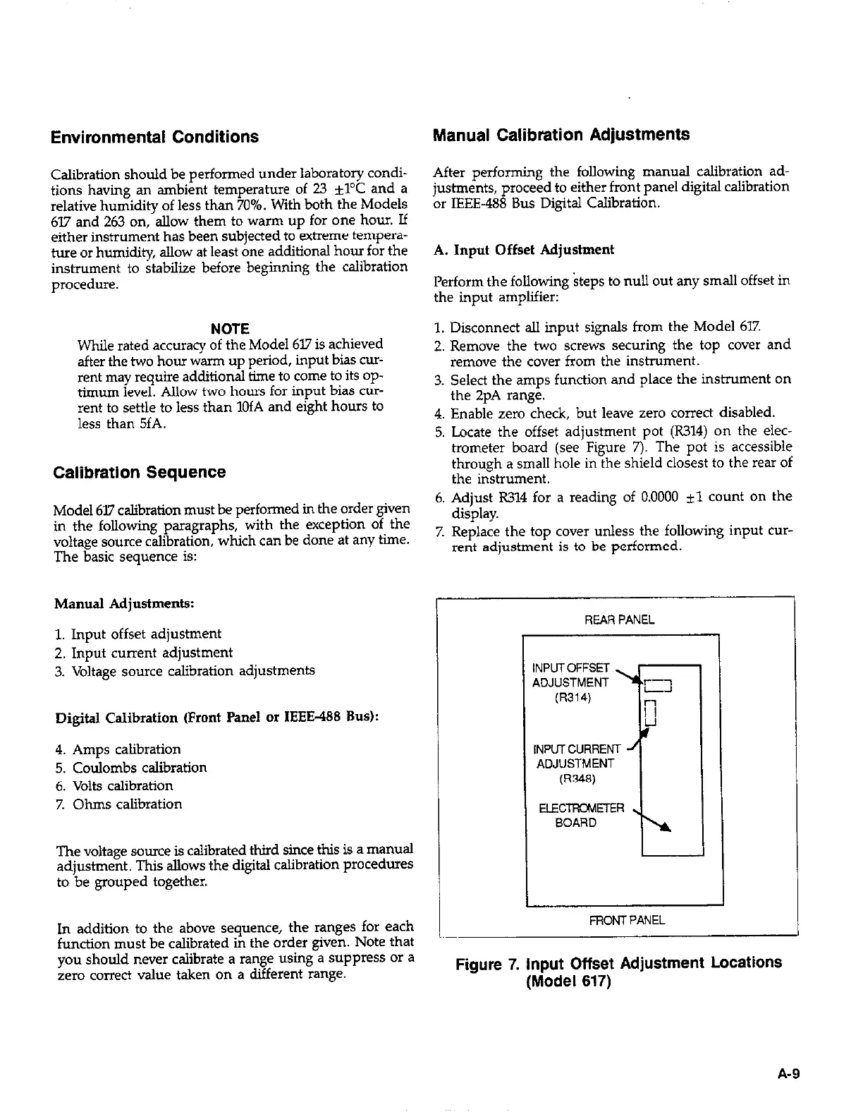
5. Locate the offset adjustment pot (R314) on the elec-
trometer board (see Figure 7). The pot is accessible
through a small hole in the shield closest to the rear of
the instrument.
6. Adjust R314 for a reading of 0.0000 il count on the
display.
7. Replace the top cover unless the following input cur-
rent adjustment is to be performed.
REAR PANEL
INPUTOFFSET
ADJUSTMENT
INPUlCURRENT
ADJUSTMENT
FRONT PANEL
Figure 7. Input Offset Adjustment Locations
(Model 617)
A-9
 Loading...


