B. Input Current Adjustment
Use the following procedure to null out any input current
in the input stage:
1. Disconnect all input signals from the Model 617. Place
the protection cap (CAp-18) on the INPUT connector.
2. Remove the two screws securing the top cover and
remove it from the instrument.
3. Place the Model 617 in the amps function and the 2pA
range.
4. Enable zero check and zero correct in that order.
5. Disconnect floating sources and connect a ground link
between the COM and chassis ground binding posts.
Disable zero check, but leave zero correct enabled.
6. Wait several minutes until the reading on the
display
settles down; about ‘I5 counts (1.5fA) p-p of noise is
normal.
7. Locate the input current pot R348 on the electrometer
board. It is accessible through a small hole in the shield
(see Figure 7).
8. Carefully adjust R348 for a reading of 0.0000 il5 counts
on the display. Iterative adjustment may be necessary.
9. Replace the top cover and secure it with the two screws
removed earlier.
C. Voltage Source Calibration
Use the following procedure to calibrate the voltage
source. Since the voltage source is independent from the
electrometer section, voltage source calibration can be per-
formed at any time.
WARNING
Hazanfous voltage will be used in Some of the
following steps.
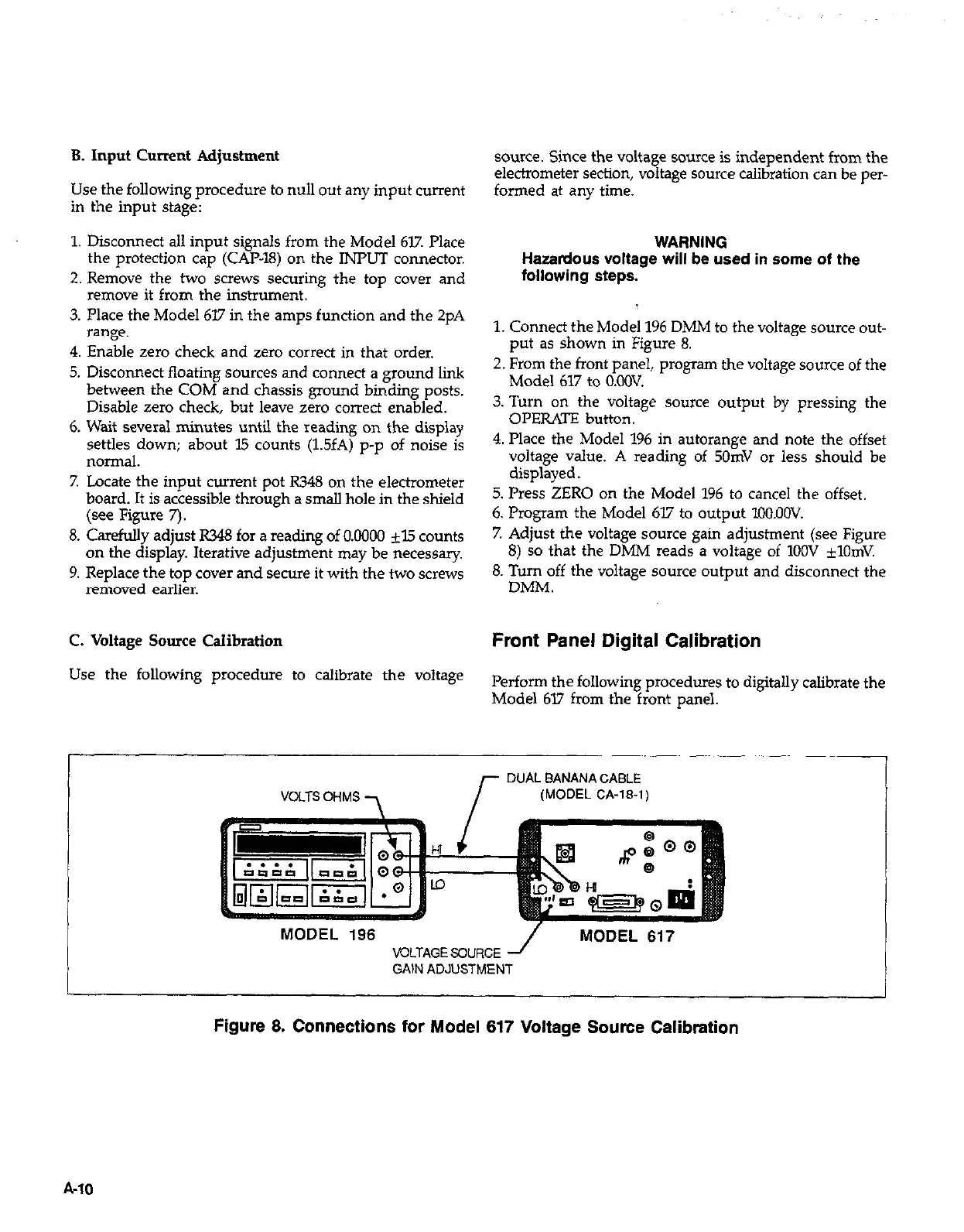
1. Connect the Model 196 DMM to the voltage source out-
put as shown in Figure 8.
2. From the front panel, program the voltage source of the
Model 617 to O.OOV.
3. Turn on the voltage source output by pressing the
OPERATE button.
4. Place the Model 196 in autorange and note the offset
voltage value. A reading of 50mV or less should be
displayed.
5. Press ZERO on the Model 196 to cancel the offset.
6. Program the Model 617 to output lOO.OOV.
7. Adjust the voltage source gain adjustment (see Figure
8) so that the DMM reads a voltage of 1OOV ilOmV.
8. Turn off the voltage source output and disconnect the
DMM.
Front Panel Digital Calibration
Perform the following procedures to digitally calibrate the
Model 617 from the front panel.
I
DUAL BANANA CABLE
(MODEL CA-l&l)
MODEL 196
VOLTAGE SOURCE
GAIN ADJUSTMENT
Figure 8. Connections for Model 617 Voltage Source Calibration
A-10
 Loading...


