3.7.2 Bus Connections
3. Add additional connectors from other instruments, as re-
quired.
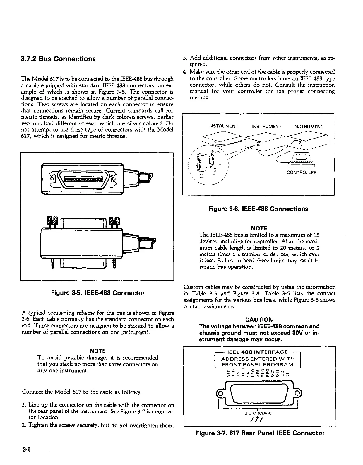
The Model 617 is to be connected to the IEEE-486 bus through
a cable equipped with standard IEEE-486 connectors, an ex-
ample of which is shown in Figure 3-5. The connector is
designed to be stacked to allow a number of parallel connec-
tions. Two screws are located on each connector to ensure
that connections remain secure. Current standards call for
metric threads, as identified by dark colored screws. Earlier
versions had different screws, which are silver colored. Do
not attempt to use these type of connectors with the Model
617, which is designed for metric threads.
4. Make sure the other end of the cable is mouerlv connected
to the controller. Some controllers have a; IEEE-488 type
connector, while others do not. Consult the instruction
manual for your controller for the proper connecting
method.
Figure 3-5. IEEE-488 Connector
A typical connecting scheme for the bus is shown in Figure
3-6. Each cable normally has the standard connector on each
end. These connectors are designed to be stacked to allow a
number of parallel connections on one instrument.
NOTE
To avoid possible damage, it is recommended
that you stack no more than three connectors on
any one instrument.
Connect the Model 617 to the cable as follows:
1. Line up the connector on the cable with the connector on
the rear panel of the instrument. See Figure 3-7 for connec-
tor location.
2. Tighten the screws securely, but do not overtighten them.
INSTRUMENT
INSTRUMENT
INSTRUMENl
CONTROLLER
Figure 3-6. IEEE-488 Connections
NOTE
The IEEE-488 bus is limited to a maximum of 15
devices, including the controller. Also, the maxi-
mum cable length is limited to 20 meters, or 2
meters times the number of devices, which ever
is less. Failure to heed these limits may result in
erratic bus operation.
Custom cables may be constructed by using the information
in Table 3-5 and Figure 3-8. Table 3-5 lists the contact
assignments for the various bus lines,~ while Figure 3-8 shows
contact assignments.
CAUTION
The voltage between IEEE-488 common and
chassis ground must not exceed 30V or in-
strument damage may occur.
r
EEE 488 ,NTERFACE
ADDRESS ENTERED WITH
1
FRONT PANEL PROGRAM
3OV MAX
rf;r
Figure 3-7. 617 Rear Panel IEEE Connector
3-g
 Loading...


