the built-in voltage source set to less than 0.6V) can be
measured using the Model 617 without regard to input vol-
tage burden. High capacitance diodes such as zener devices
will present no problem, since the Model 617 is unaffected
by stray capacitance up to O.OlpF.
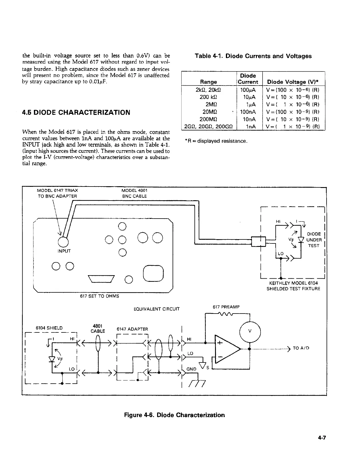
4.5 DIODE CHARACTERIZATION
When the Model 617 is placed in the ohms mode, constant
current values between In4 and lC@A are available at the
INPUT jack high and low terminals, as shown in Table 4-l.
(Input high sources the current). These currents can be used to
plot the I-V (current-voltage) characteristics over a substan-
tial range.
Table 4-I. Diode Currents and Voltages
Diode
Range
Current Diode Voltage (VP
2kQ. 20kfI
lOOpA V=(lOO x 10-61 (f?)
200 kCl
lOpA V=( 10 x 10-q (RI
2MQ
14
v=( 1 x 1041 (RI
ZOMR
. lOOnA V=(lOO x 10-q (RI
200MQ
1OnA V=( 10 x 10-q (RI
2GR, 20GQ, 200GD
1nA V=( 1 x 10-?(R)
*R = displayed resistance.
MODEL 6147 TRIAX
MODEL 4601
TO BNC ADAPTER BNC CABLE
‘I
INPVT
0
00
r-1
617 SET TO OHMS
EQUIVALENT CIRCUIT
r-----
1
l--L---i
KEITHLEY MODEL 6104
SHIELDED TEST FIXTURE
617 PREAMP
6104 SHlELD
Figure 4-6. Diode Characterization
4-7
 Loading...


