Table 3-5. IEEE Contact Designations
contact
IEEE-488
Uumber
Designation
1
DlOl
2
D102
3
D103
4
Di04
5 EOI 1241”
6
DAV
7
NRFD
8 NDAC
9 IFC
10
SRQ
11
ATN
12
SHIELD
13
D105
14
D106
15 D107
16
D108
17
REN (24)’
18 Gnd, (6)*
19
Gnd, (7)*
20
Gnd, (8)”
21
Gnd, (9)”
22
Gnd, (101’
23 Gnd, (111*
24
Gnd, LOGIC
Type
Data
Data
Data
Data
Management
Handshake
Handshake
Handshake
Management
Management
Management
Ground
Data
Data
Data
Data
Management
Ground
Ground
Ground
Ground
Ground
Ground
Ground
*Number in parenthesis refer to signal
ground return of referenced contact
number. EOI and REN signal lines return on
contact 24.
I
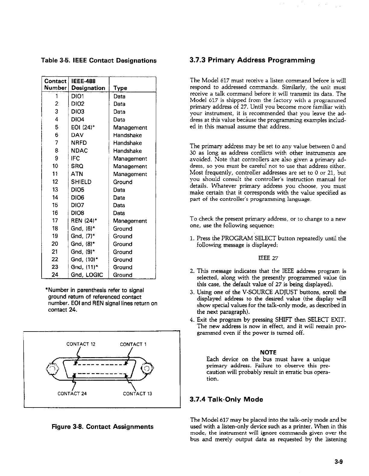
CONTACT 12 CONTACT 1 I
CONTiCT 24
CONiACT 13
I
Figure 3-8. Contact Assignments
3.7.3 Primary Address Programming
The Model 617 must receive a listen command before is will
respond to addressed commands. Similarly, the unit must
receive a talk command before it will transmit its data. The
Model 617 is shipped from the factory with a programmed
primary address of 27. Until you become more familiar with
your instrument, it is recommended that you leave the ad-
dress at this value be&se the programming examples includ-
ed in this manual a~wme that address.
The primary address may be set to any value between 0 and
30 as long as address conflicts with other instruments are
avoided. Note that controllers are also given a primary ad-
dress, so you must be careful not to use that address either.
Most frequently, controller addresses are set to 0 or 21, but
you should consult the controller’s instruction manual for
details. Whatever primary address you choose, you must
make certain that it corresponds with the value specified as
part of the controller’s programming language.
To check the present primary address, or to change to a new
one, use the following sequence:
1. Press the PROGRAM SELECT button repeatedly until the
following message is displayed:
IEEE 27
2. This message indicates that the IEEE address program is
selected, along with the presently programmed value (in
this case, the default value of 27 is being displayed).
3. Using one of the V-SOURCE ADJUST buttons, scroll the
displayed address to the desired value (the display will
show special values for the talk-only mode, as described in
the next paragraph).
4. Exit the program by pressing SHIFT then SELECT EXIT.
The new address is now in effect, and it will remain pro-
grammed even if the power is turned off.
NOTE
Each device on the bus must have a unique
primary address. Failure to observe this pre-
caution will probably result in erratic bus opera-
tion.
3.7.4 Talk-Only Mode
The Model 617 may be placed into the talk-only mode and be
used with a listen-only device such as a printer. When in this
mode, the instrument will ignore commands given over the
bus and merely output data as requested by the listening
3-S
 Loading...


