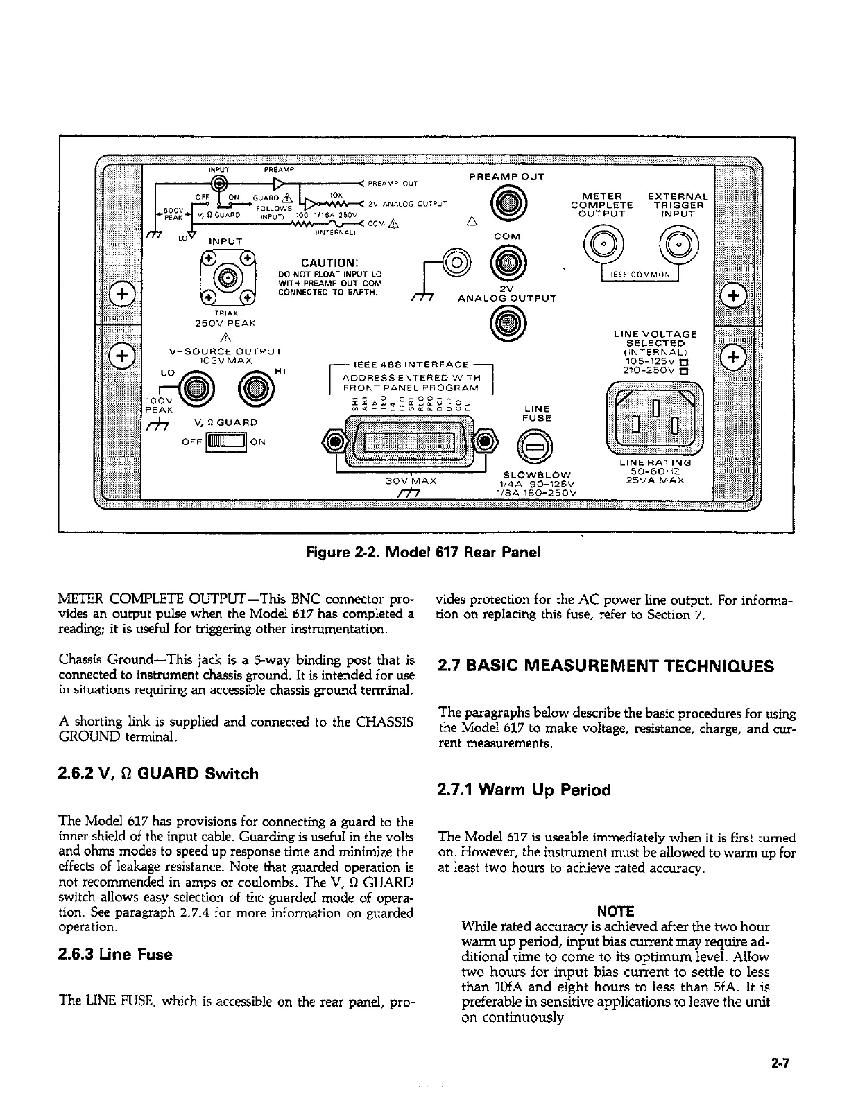
Figure 2-2. Model 617 Rear Panel
METER COMPLETE OUTPUT-This BNC connector prc-
vides an output pulse when the Model 617 has completed a
reading; it is useful for triggeling other instrumentation.
Chassis Ground-This jack is a s-way biding post that is
connected to instrument chassis ground. It is intended for use
in situations requiring an accessible chassis ground terminal.
A shorting link is supplied and connected to the CHASSIS
GROUND terminal.
vides protection for the AC power line output. For infcrma-
ticn on replacing this fuse, refer to Section 7.
2.7 BASIC MEASUREMENT TECHNIQUES
The paragraphs below describe the basic procedures for using
the Model 617 to make voltage, resistance, charge, and cur-
rent measurements.
2.6.2 V, !I GUARD Switch
2.7.1 Warm Up Period
The Model 617 has provisions for connecting a guard to the
inner shield of the input cable. Guarding is useful in the volts
and ohms modes to speed up response time and minimize the
effects of leakage resistance. Note that guarded operation is
not recommended in amps or coulombs. The V, Q GUARD
switch allows easy selection of the guarded mode of cpera-
ticn. See paragraph 2.7.4 for more information on guarded
operation.
2.6.3 Line Fuse
The LINE FUSE, which is accessible on the rear panel, pro
The Model 617 is usable immediately when it is first turned
on. However, the instrument must be allowed to warm up for
at least two hours to achieve rated accuracy.
NOTE
While rated accuracy is achieved after the two hour
wan-n up period, input bias current may require ad-
ditional time to come to its optimum level. Allow
two hours for input bias current to settle to less
than 1OfA and eight hours to less than 5fA. It is
preferable in sensitive applications to leave the unit
on continuously.
2-7
 Loading...


