SECTION 7
MAINTENANCE
7.1 INTRODUCTION
5. Replace the top cover and connect the instrument to the
power line.
This section contains information necessary to maintain,
calibrate, and troubleshoot the Model 617. Fuse replacement
and line voltage selection procedures are also included.
WARNING
The procedures included in this section ere
for use only by qualified service personnel.
Do not perform these procedures unless
qualified to do so. Many of the steps in this
section may expose you to potentially
lethal voltages that could result in personal
injury or death if normal safety precautions
are not observed.
7.2 LINE VOLTAGE SELECTION
The Model 617 may be operated from either 105-125V or
210-250V 50 or 6OHz power sources. A special transfomer
may be installed for 90-1lOV and 195~235V ranges. The in-
strument was shipped from the factory set for an operating
voltage marked on the rear panel. To change the line voltage,
proceed as follows:
WARNING
Disconnect the Model 617 from the power
line and all other sources before removing
the top cover.
1. Remove the screws securing the top cover to the rear panel
and carefully lift the cover away from the instrument.
2. Locate the line voltage switch adjacent to the POWER
switch on the mother board. Place the switch in the correct
position, as outlined in Table 7-l.
3. Install a fuse consistent with the operating voltage, as
described in paragraph 7.3.
CAUTION
The correct fuse type must be used to main-
tain proper instrument protection.
4. Mark the selected line voltage on the rear panel for future
reference (to avoid confusion, erase the old mark).
Table 7-l. Line Voltage Selection l50-60Hz)
*Requires special power transformer.
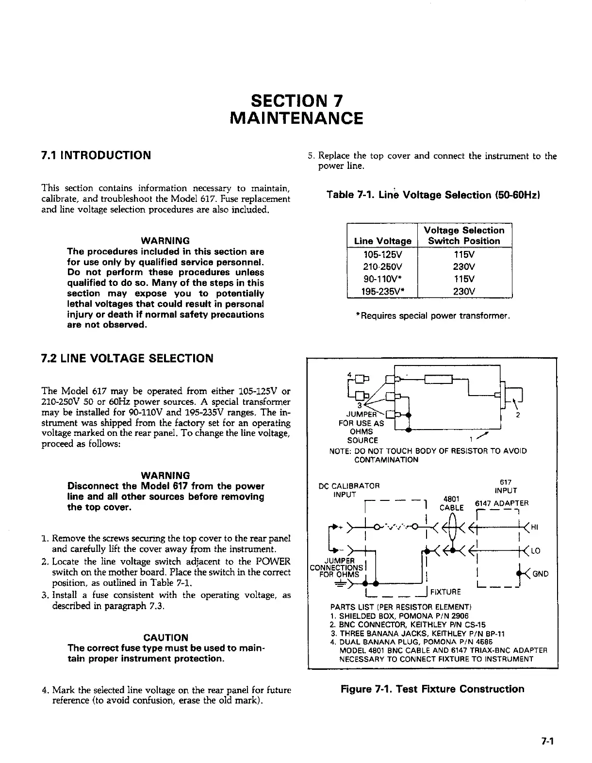
NOTE DO NOT TOUCH BODY OF RESlsrDR TO AVOID
CONTAMINATION
DC CALIBRATOR
617
INPUT
INPUT
AF,XT”RE L---
PARTS LIST (PER RESISTOR ELEMENT!
_~. ,~ _.~ _... ~. ~_~~~~~
1. SHIELDED BOX, POMONA P/N 2906
2. BNC CONNECTOR, KEITHLEY P/N CS-15
3. THREE BANANA JACKS, KEITHLN P/N BP-,,
4. DUAL BANANA PLUG, POMONA PIN 4595
MODEL 480, BNC CABLE AND 6147 TRIAX-BNC ADAPTER
NECESSARY TO CONNECT FIXTURE TO lNSTRUMENT
Figure 7-1. Test Fixture Construction
7-1
 Loading...


