FEEDBACK
AND
/
SWITCHING
\
SIGNAL SIGNAL
INPUT
STAGE
\
GAIN
STAGE
\
OUTPUT
lNPUT lNPUT
/
STAGE
103081 iu3091
(0301. 0302.a3071
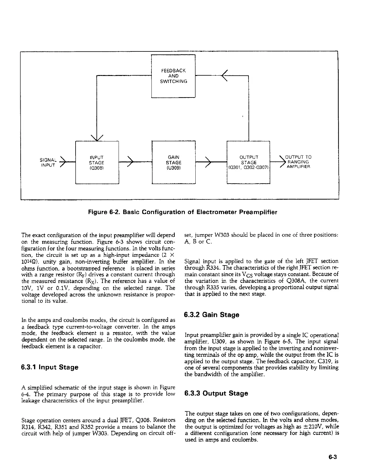
Figure 6-2. Basic Configuration of Electrometer Preamplifier
The exact configuration of the input preamplifier will depend
on the measuring function. Figure 6-3 shows circuit con-
figuration for the four measuring functions. In the volts func-
tion, the circuit is set up as a high-input impedance (2 X
1014n). unity gain, non-inverting buffer amplifier. In the
ohms function. a bootstrapped reference is placed in series
with a range resistor (RF) drives a constant current through
the measured resistance (Rx). The reference has a value of
lOV, 1V or O.lV, depending on the selected range. The
voltage developed across the unknown resistance is propor-
tional to its value.
In the amps and coulombs modes, the circuit is configured as
a feedback type current-to-voltage converter. In the amps
mode, the feedback element is a resistor, with the value
dependent on the selected range. In the coulombs mode, the
feedback element is a capacitor.
6.3.1 Input Stage
A simplified schematic of the input stage is shown in Figure
6-4. The primary purpose of this stage is to provide low
leakage characteristics of the input preamplifier.
Stage operation centers around a dual JFET, Q308. Resistors
R314, R342, R351 and R352 provide a means to balance the
circuit with help of jumper W303. Depending on circuit off-
set, jumper W303 should be placed in one of three positions:
A, B or C.
Signal input is applied to the gate of the left JFET section
through R334. The characteristics of the right JFET section re-
main constant since its VGS voltage stays constant. Because of
the variation in the characteristics of Q308A, the current
through R335 varies, developing a proportional output signal
that is applied to the next stage.
6.3.2 Gain Stage
Input preamplifier gain is provided by a single IC operational
amplifier, U309, as shown in Figure 6-5. The input signal
from the input stage is applied to the inverting and noninver-
ting terminals of the op amp, while the output from the IC is
applied to the output stage. The feedback capacitor, C319, is
one of several components that provides stability by limiting
the bandwidth of the amplifier.
6.3.3 Output Stage
The output stage takes on one of two configurations, depen-
ding on the selected function. In the volts and ohms modes,
the output is optimized for voltages as high as +21OV, while
a different configuration (one necessary for high current) is
used in amps and coulombs.
6-3
 Loading...


