At low signal levels, noise may affect accuracy. Shielding of
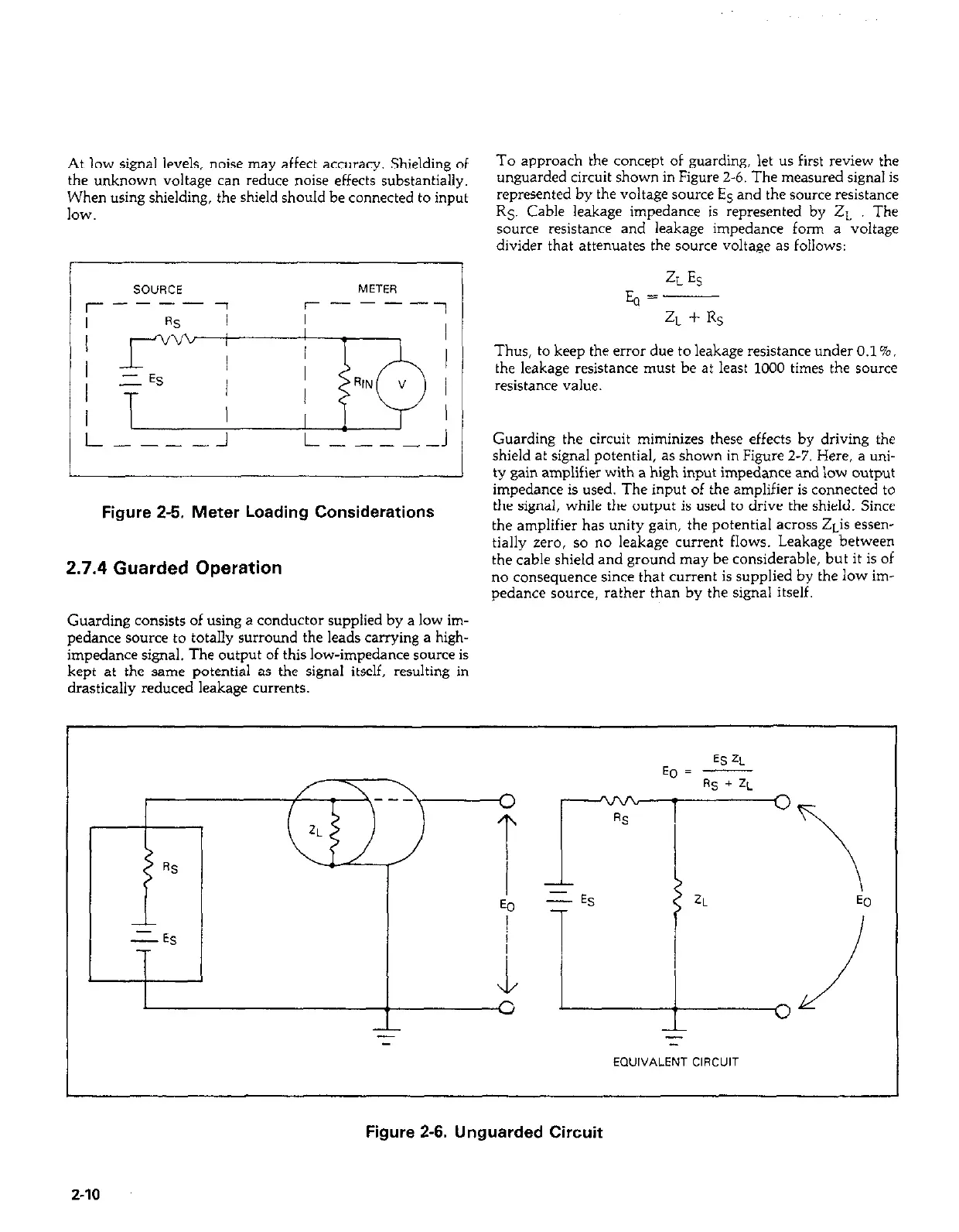
To approach the concept of guarding, let us first review the
the unknown voltage can reduce noise effects substantially.
unguarded circuit shown in Figure 2-6. The measured signal is
When using shielding, the shield should be connected to input
represented by the voltage source ES and the source resistance
IOW.
RS. Cable leakage impedance is represented by 2~ The
source resistance and leakage impedance form a voltage
divider that attenuates the source voltage as follows:
r-
I
/
t-
T ; / N”!
G-lJ
J
---- J
L-----J
Figure 2-5. Meter Loading Considerations
2.7.4 Guarded Operation
ZLES
E, =
ZL + Rs
Thus, to keep the error due to leakage resistance under O.l%,
the leakage resistance must be at least 1000 times the source
resistance value.
Guarding the circuit miminizes these effects by driving the
shield at signal potential, as shown in Figure 2-7. Here, a uni-
ty gain amplifier with a high input impedance and low output
impedance is used. The input of the amplifier is connected to
the signal, while the output is used to drive the shield. Since
the amplifier has unity gain, the potential across ZLis essen-
tially zero, so no leakage current flows. Leakage between
the cable shield and ground may be considerable, but it is of
no consequence since that current is supplied by the low im-
pedance source, rather than by the signal itself.
Guarding consists of using a conductor supplied by a low im-
pedance source to totally surround the leads carrying a high-
impedance signal. The output of this low-impedance source is
kept at the same potential as the signal itself, resulting in
drastically reduced leakage currents.
Figure 2-6. Unguarded Circuit
2-10
 Loading...


