1
-I
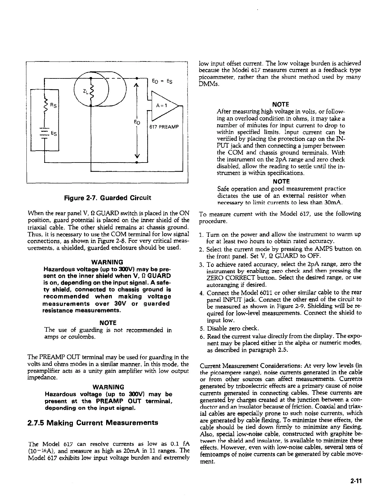
Figure 2-7. Guarded Circuit
When the rear panel V, Q GUARD switch is placed in the ON
position, guard potential is placed on the inner shield of the
triaxial cable. The other shield remains at chassis ground.
Thus, it is necessary to use the COM terminal for low signal
connections, as shown in Figure 2-0. For very critical meas-
urements, a shielded, guarded enclosure should be used.
WARNING
Hazardous voltage lup to 3OOV) may be pre-
sent on the inner shield when V, Q GUARD
is on, depending on the input signal. A safe-
ty shield, connected to chassis ground is
recommended when making voltage
measurements over 30V or guarded
resistance measurements.
NOTE
The use of guarding is not recommended in
amps or coulombs.
The PREAMI’ OLJT terminal may be used for guarding in the
volts and ohms modes in a similar manner. In this mode, the
preamplifier acts as a unity gain amplifier with low output
impedance.
WARNING
Hazardous voltage (up to 3WV) may be
present at the PREAMP OUT terminal,
depending on the input signal.
2.7.5 Making Current Measurements
The Model 617 can resolve currents as low as 0.1 fA
(lo--lbA), and measure as high as 2011~4 in 11 ranges. The
Model 617 exhibits low input voltage burden and extremely
low input offset current. The low voltage burden is achieved
because the Model 617 measures current as a feedback type
picoammeter, rather than the shunt method used by many
DMMs.
NOTE
After measuring high voltage in volts, or follow-
ing an overload condition in ohms, it may take a
number of miriutes for input current to drop to
within specified limits. Input current can be
verified by placing the protection cap on the IN-
PUT jack and then connecting a jumper between
the COM and chassis ground terminals, With
the instrument on the 2pA range and zero check
disabled, allow the reading to settle until the in-
strument is within specifications.
NOTE
Safe operation and good measurement practice
dictates the use of an external resistor when
necessary to limit currents to less than 3011~4.
To measure current with the Model 617, use the following
procedure.
I. Turn on the power and allow the instrument to warm up
for at least two hours to obtain rated accuracy.
2. Select the current mode by pressing the AMPS button on
the front panel. Set V, Q GUARD to OFF.
3. To achieve rated accuracy, select the 2pA range, zero the
instrument by enabling zero check and then pressing the
ZERO CORRECT button. Select the desired range, or use
autoranging if desired.
4. Connect the Model 6011 or other similar cable to the rear
panel INPUT jack. Connect the other end of the circuit to
be measured as shown in Figure 2-9. Shielding will be re-
quired for low-level measurements. Connect the shield to
input low.
5. Disable zero check.
6. Read the current value directly from the display. The expo-
nent may be placed either in the alpha or numeric modes,
as described in paragraph 2.5.
Current Measurement Considerations: At very low levels (in
the picoampere range), noise currents generated in the cable
or from other sources can affect measurements. Currents
generated by triboelectric effects are a primary cause of noise
currents generated in connecting cables. These currents are
generated by charges created at the junction between a con-
ductor and an insulator because of friction. Coaxial and triax-
ial cables are especially prone to such noise currents, which
are generated by cable flexing. To minimize these effects, the
cable should be tied down firmly to minimize any flexing.
Also, special low-noise cable, constructed with graphite be-
tween the shield and insulator, is available to minimize these
effects. However, even with low-noise cables, several tens of
femtoamps of noise currents can be generated by cable move-
ment.
2-11
 Loading...


