2. Place the Model 617 on the volts function and 200mV
range.
3. Zero correct the Model 617 by enabling zero check and
zero correct in that order.
4. Program the Model 263 to output Cil.ooOmV and release
zero check on the Model 617.
5. Ze~peQisplay of the Model 617 by pressing
6. Program the Model 263 to output 19O.OOOmV.
7. Adjust the display of the Model 6l7 to read 19O.OOmV
using the ADIUST buttons on the Model 617.
8. Pro&m the Model 263 to output OO.OOCmV by press-
ing ZERO.
9. On the Model 6l7, disable zero correct and suppress.
10. Using Table 6 as a guide, repeat steps 3 through 9 for
the 2V and 2OV ranges.
11. With the Model 343A set to zero volts, connect it to the
Model 263 as shown in Figure 10. Leave the Model 263
connected to the Model 617 as shown in Figure 9.
12. Select the 2OOV range and zero correct the Model 617
by enabling zero check and zero correct in that order.
13. Set the Model 343A to output 19O.OOOV to the Model
263.
14. Release zero check on the Model 617, and program the
Model 263 to output the external voltage source by
pressing SHBT VOLTS.
15. Adjust the display of the Model 617 to read 19O.OOV
using the ADJUST buttons of the Model 617.
16. Place the Model 263 and the Model 343A in standby.
17. On the Model 6l7, disable zero correct.
18. Turn off the Model 343A and disconnect it from the
Model 263.
1. Connect the Model 263 to the Model 617 as shown in
Figure 8. Note that Model 263 COMMON must be con-
nected to Model 617 COMMON.
2. Enable GUARD on the Model 263 and set the Model
617 guard switch to the “ON” position.
3. Place the Model 617 in the ohms function and 20GQ
range.
4. Zero correct the Model 617 by enabling zero check and
zero correct in that order.
5. Program the Model 263 to output the 1OGQ resistor. The
actual value of that resistor will be displayed by the
Model 263.
6. Release zero check on the Model 617 and allow the
resistor reading to settle.
7. Adjust the display, using the ADJUST buttons of the
Model 617, to correspond to the reading on the Model
263.
8. Disable guard on the Model 263 and set the Model 637
guard switch to the “OFF” position.
9. Using Table 7 as a guide, repeat steps 4 through 7 for
the ZOOMS, 2MQ, and 200kO ranges.
10. Set the Model 617 to the 20kR range.
11. Zero correct the Model 617 by enabling zero check and
zero correct in that order.
12. Set the Model 263 to the 1OkQ range and press ZERO
to source zero ohms to the Model 617.
13. Release zero check on the Model 617. The reading on
its display is test lead resistance and zero offset.
14. Enable suppress on the Model 617 to zero the display.
15. Press ZERO on the Model 263 to source 1OkO to the
Model 263. The actual value of that resistor will be
displayed by the Model 263.
16. Adjust the displayed reading on the Model 677 to cor-
respond to the reading on the Model 263.
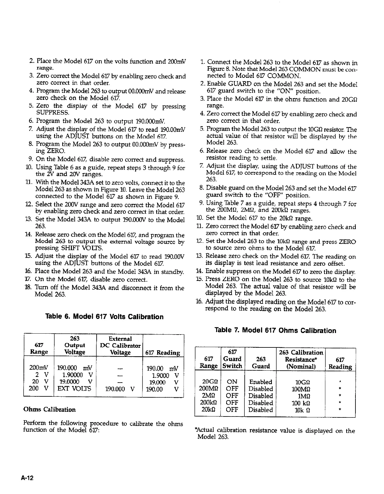
Table 6. Model 617 Volts Calibration
Table 7. Model 617 Ohms Calibration
263
617
output
Range Voltage
2OOmV
190.000 mV
2v
1.90000 v
20 v
19.0000 v
200 V EXT VOUS
T
Ohms Calibration
External
DC Calibrator
Voltage
617 Reading
190.00 mV
-
1.9000 v
-
19.MKl v
190.000 v
190.00 v
L
Perform the following procedure to calibrate the ohms
function of the Model 617:
617
263 Calibration
617 Guard 263
Resistance*
617
Range Switch
Guard
(Nominal)
Reading
ZOGO ON
Enabled
1OGD
t
2OOMQ OFF Disabled
lOOM0
t
2MQ
OFF Disabled
1Ml-l *
2OOkQ OFF Disabled
100 kO
l
20kQ
OFF Disabled
1Ok Q
*
/ I I
1
1
*Actual calibration resistance value is displayed on the
Model 263.
A-12
 Loading...


