2.10 USING EXTERNAL FEEDBACK
External feedback provides a means to extend the capabilities
of the Model 617 Electrometer to such uses as logarithmic cur-
rents, non-decade current ranges, as well as non-standard
coulombs ranges. The following paragraphs discuss the basic
electrometer input circuitry and methods to implement these
functions.
2.10.1 Electrometer Input Circuitry
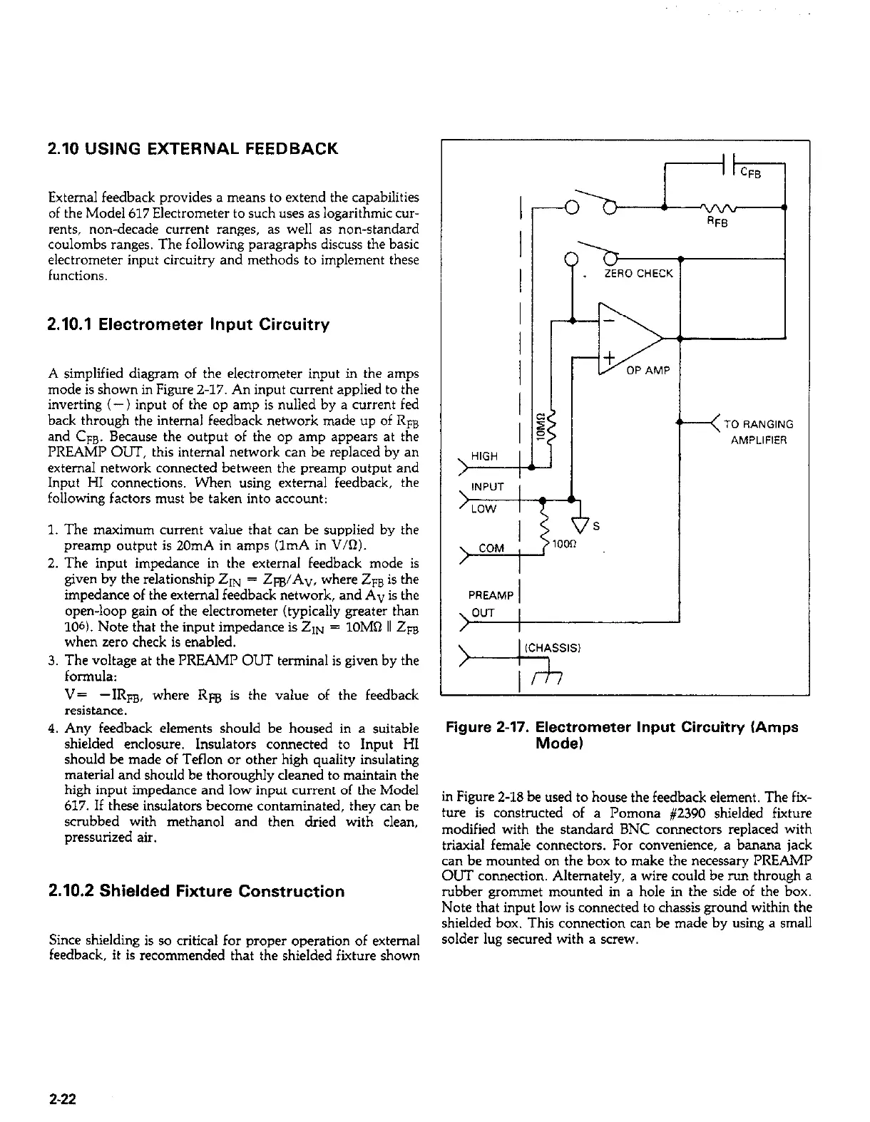
A simplified diagram of the electrometer input in the amps
mode is shown in Figure 2-17. An input current applied to the
inverting (-) input of the op amp is nulled by a current fed
back through the internal feedback network made up of Rm
and CFB. Because the output of the op amp appears at the
PREAMP OUT, this internal network can be replaced by an
external network connected between the preamp output and
Input HI connections. When using external feedback, the
following factors must be taken into account:
1. The maximum current value that can be suppiied by the
preamp output is 20mA in amps (1mA in V/R).
2. The input impedance in the external feedback mode is
given by the relationship 21~ = Z@A”, where Zm is the
impedance of the external feedback network, and A” is the
open-loop gain of the electrometer (typically greater than
106). Note that the input impedance is ZIN = lOM0 II 2~
when zero check is enabled.
3. The voltage at the PREAMI’ OUT terrrtinal is given by the
formula:
V= -IRFB, where Rm is the value of the feedback
resistance.
4. Any feedback elements should be housed in a suitable
shielded enclosure. Insulators connected to Input HI
should be made of Teflon or other high quality insulating
material and should be thoroughly cleaned to maintain the
high input impedance and low input current of the Model
617. If these insulators become contaminated, they can be
scrubbed with methanol and then dried with clean,
pressurized air.
2.10.2 Shielded Fixture Construction
Since shielding is so critical for proper operation of external
feedback, it is recommended that the shielded fixture shown
Figure 2-17. Electrometer Input Circuitry (Amps
Mode)
in Figure 2-18 be used to house the feedback element. The fix-
ture is constructed of a Pomona #2390 shielded fixture
modified with the standard BNC connectors replaced with
triaxial female connectors. For convenience, a banana jack
can be mounted on the box to make the necessary PREAMP
OUT connection. Alternately, a wire could be ru11 through a
rubber grommet mounted in a hole in the side of the box.
Note that input low is connected to chassis ground within the
shielded box. This connection can be made by using a small
solder lug secured with a screw.
2-22
 Loading...


