4. CONSTRUCTION
FEEDBACK
1,
’ ’ PREAMP OVT
1
I
I
HI
HI
A A
LO
IlV I-
I
/I
TO RANGING
I
\ LO
AMP AND AID
I
I
/I
GND) -
GND
-- ---
617 lNP”T AMP
--v--J PoMoNAsoX -
s
PARTS LIST
IT:, OESCRlPTlON MFR. PART NUMBER
SHIELDED FIXTURE POMONA “2390
2 FEMALE TRIAXIAL KEITHLEY CS-181
3 SANANPl JACK WTHLEY W-9-2
4 TRlAXlAL CABLE KElTHLEY 6011
5 TRIAXIAL CABLE KEITHLEY ,024
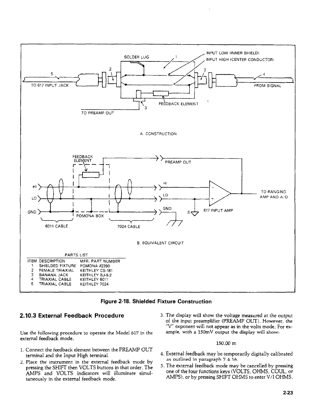
Figure 2-18. Shielded Fixture Construction
2.10.3 External Feedback Procedure
3. The display will show the voltage measured at the output
of the input preamplifier (PREAMP OUT). However, the
“V exponent will not appear as in the volts mode. For ex-
Use the following procedure to operate the Model 617 in the
ample, with a 150mV output the display will show:
external feedback mode.
150.00 m
1. Connect the feedback element between the PREAMP OUT 1. Connect the feedback element between th
terminal and the Input High terminal. terminal and the Input v4-h +--in=’
4. External feedback may be temporarily digitally calibrated
2. Place the instrument in LX CXKJXWZ~ x 2. Place the instrument in the external feedback mode by
as outlined in paragraph 7.4.16.
pressing the SHIFT then VOLTS buttons pressing the SHIFT then VOLTS buttons in that order. The
5. The external feedback mode may be cancelled by pressing
AMPS and VOLTS indicators will i AMPS and VOLTS indicators will illuminate simul-
one of the four functions keys (VOLTS, OHMS, COUL, or
taneously in the external feedback mode taneously in the external feedback mode.
AMPS), or by pressing SHIFT OHMS to enter V/I OHMS.
2-23 2-23
 Loading...


