6.6 DIGITAL CIRCUITRY
Model 617 operation is controlled by the internal microcom-
puter and associated software. The following paragraphs
briefly describe the various aspects of the digital circuitry.
Descriptions are keyed to the digital circuitry schematic
(drawing number 617-106, page 2) located at the end of Sec-
tion 8.
Device selection is performed by elements of Ulll, U112,
U117, and U118. MPU lines used are part of the selection pro-
cess include the AlO-A12 address lines, the PB6 line, the I’B7
line, and the DS line. Signals generated by this circuitry in-
clude a line which controls the ROM chip select, a signal line
that controls the RAM chip select, and circuitry which
enables the display control and IEEE-488 bus circuits. Addi-
tional device selection signals include the memory paging
signals. Two signals divide the 16K ROM area into 4K pages,
while the a third signal divides the 2K RAM area into two 1K
pages.
6.6.1 Microcomputer
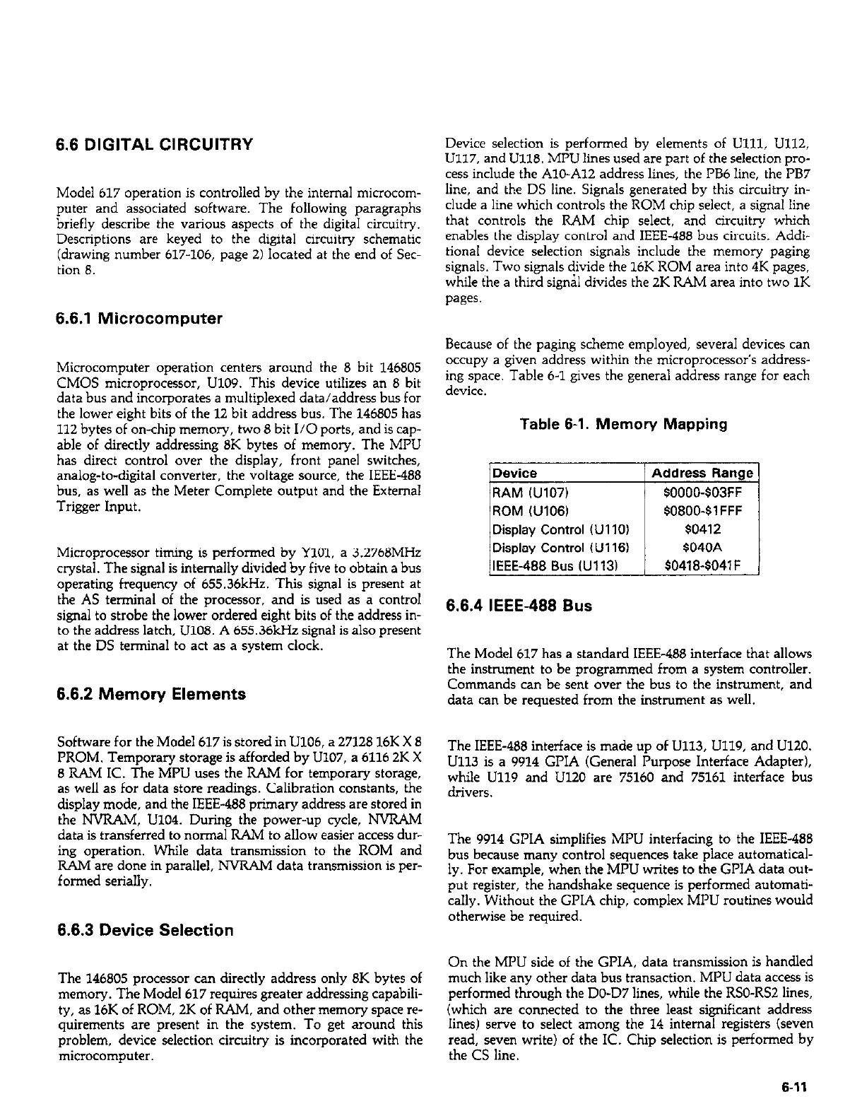
Because of the paging scheme employed, several devices can
Microcomputer operation centers around the 8 bit 146805
occupy a given’acidr&s within the &croprocessor’s address-
CMOS microprocessor, U109. This device utilizes an 8 bit
ing space. Table 6-1 gives the general address range for each
data bus and incorporates a multiplexed data/address bus for
device.
the lower eight bits of the 12 bit address bus. The 146805 has
112 bytes of on-chip memory, two 8 bit I/O ports, and is cap-
Table 6-1. Memory Mapping
able of directly addressing 8K bytes of memory. The MPU
has direct control over the display, front panel switches,
analog-to-digital converter, the voltage source, the IEEE-488
bus, as well as the Meter Complete output and the External
Trigger Input.
the AS terminal of the processor, and is used as a control
signal to strobe the lower ordered eight bits of the address in-
to the address latch. U108. A 655.36kHz sienna1 is also oresent
Microprocessor timing is performed by YlOl, a 3.2768MHz
at the DS terminal to act as a system clock.
crystal. The signal is internally divided by five to obtain a bus
operating frequency of 655.36kHz. This signal is present at
6.6.2 Memory Elements
Commands can be s&t over the bus to the instrument, and
data can be requested from the instrument as well.
6.6.4 IEEE-488 Bus
The Model 617 has a standard IEEE-488 interface that allows
the instrument to be programmed from a system controller.
Software for the Model 617 is stored in U106, a 27128 16K X 8
PROM. Temporary storage is afforded by U107, a 6116 2K X
6 RAM IC. The MPU uses the RAM for temporary storage,
as well as for data store readings. Calibration constants, the
display mode, and the IEEE-486 primary address are stored in
the NVRAM, UlO4. During the power-up cycle, NVRAM
data is transferred to normal RAh4 to allow easier access dur-
ing operation. While data transmission to the ROM and
RAM are done in parallel, NVRAM data transmission is per-
formed serially.
6.6.3 Device Selection
The IEEE-468 interface is made up of Ull3, U119, and U120.
U113 is a 9914 GPIA (General Purpose Interface Adapter),
while U119 and U120 are 75160 and 75161 interface bus
drivers.
The 9914 GPIA simplifies MPU interfacing to the IEEE-488
bus because many control sequences take place automatical-
ly. For example, when the MPU writes to the GPIA data out-
put register, the handshake sequence is performed automati-
cally. Without the GPIA chip, complex MPU routines would
otherwise be required.
On the MPU side of the GPIA, data transmission is handled
The 146805 processor can directly address only 8K bytes of
much like any other data bus transaction. MPU data access is
memory. The Model 617 requires greater addressing capabili-
performed through the DO-D7 lines, while the RSO-RS2 lines,
ty, as 16K of ROM, 2K of RAM, and other memory space re- (which are connected to the three least significant address
quirements are present in the system. To get around this
lines) serve to select among the 14 internal registers (seven
problem, device selection circuitry is incorporated with the
read, seven write) of the IC. Chip selection is performed by
microcomputer. the CS line.
6-11
 Loading...


