(U137B). When the Q4 output of the clock generator (IJ127)
goes high; the output of U135B is low, the Ql output of
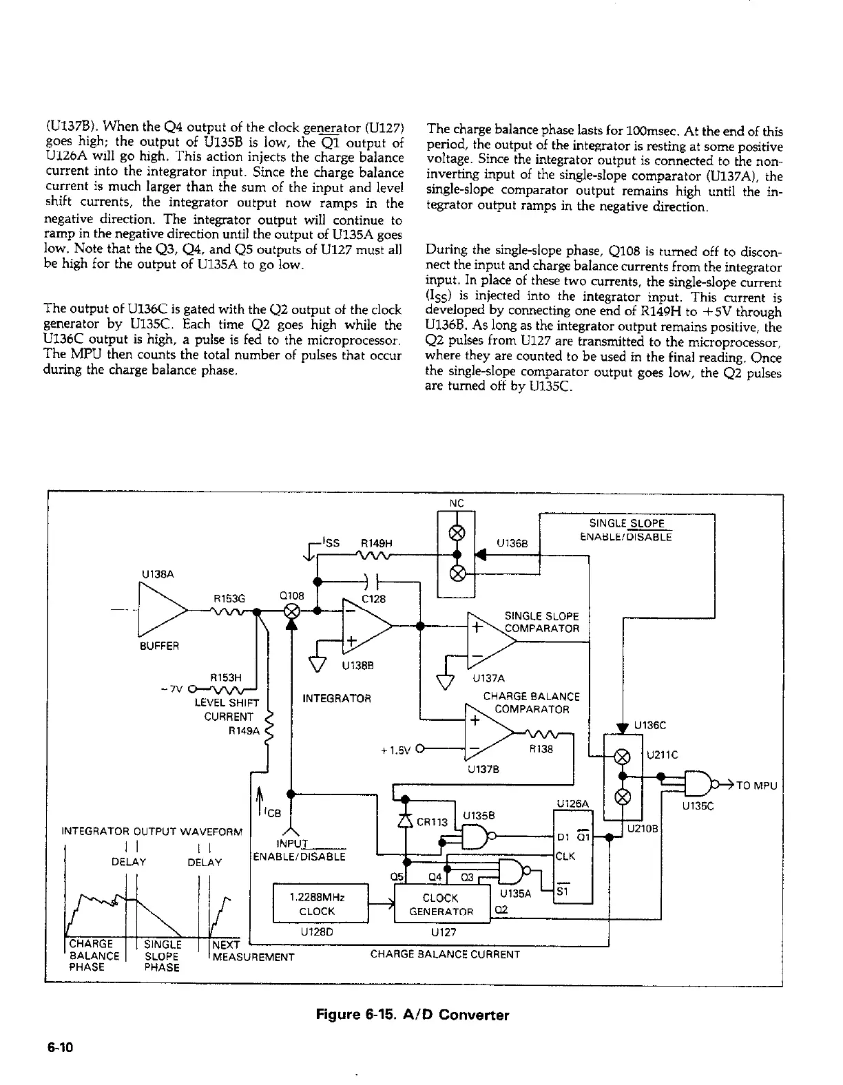
U126A will go high. This action injects the charge balance
current into the integrator input. Since the charge balance
current is much larger than the sum of the input and level
shift currents, the integrator output now ramps in the
negative direction. The integrator output will continue to
ramp in the negative direction until the output of U135A goes
low. Note that the Q3, Q4, and Q5 outputs of U127 must all
be high for the output of U135A to go low.
The output of U136C is gated with the Q2 output of the clock
generator by U135C. Each time Q2 goes high while the
U136C output is high, a pulse is fed to the microprocessor.
The MPU then counts the total number of pulses that occur
during the charge balance phase.
The charge balance phase lasts for 100msec. At the end of this
period, the output of the integrator is resting at sane positive
voltage. Since the integrator output is connected to the non-
inverting input of the single-slope comparator (U137A1, the
single-slope comparator output remains high until the in-
tegrator output ramps in the negative direction.
During the single-slope phase, QlO8 is turned off to discon-
nect the input and charge balance currents from the integrator
input. In place of these two currents, the single-slope current
(I,,) is injected into the integrator input. This current is
developed by connecting one end of R149H to +5V through
U136B. As long as the integrator output remains positive, the
Q2 pulses from U127 are transmitted to the microprocessor,
where they are counted to be used in the final reading. Once
the single-slope comparator output goes low, the Q2 pulses
are turned off by Ul35C.
CHARGE
SINGLE
BALANCE
SLOPE
PHASE
PHASE
NEXT
MEAS
INTEGRATOR OUTPVT WA”EFORM
I
I I
I I
DELAY DELAY
UREMENT
CHARGE BALANCE CVRRENT
Figure 6-15. AID Converter
,
 Loading...


