I+ I
vs= j
>
TO A/D CONVERTER
T- I
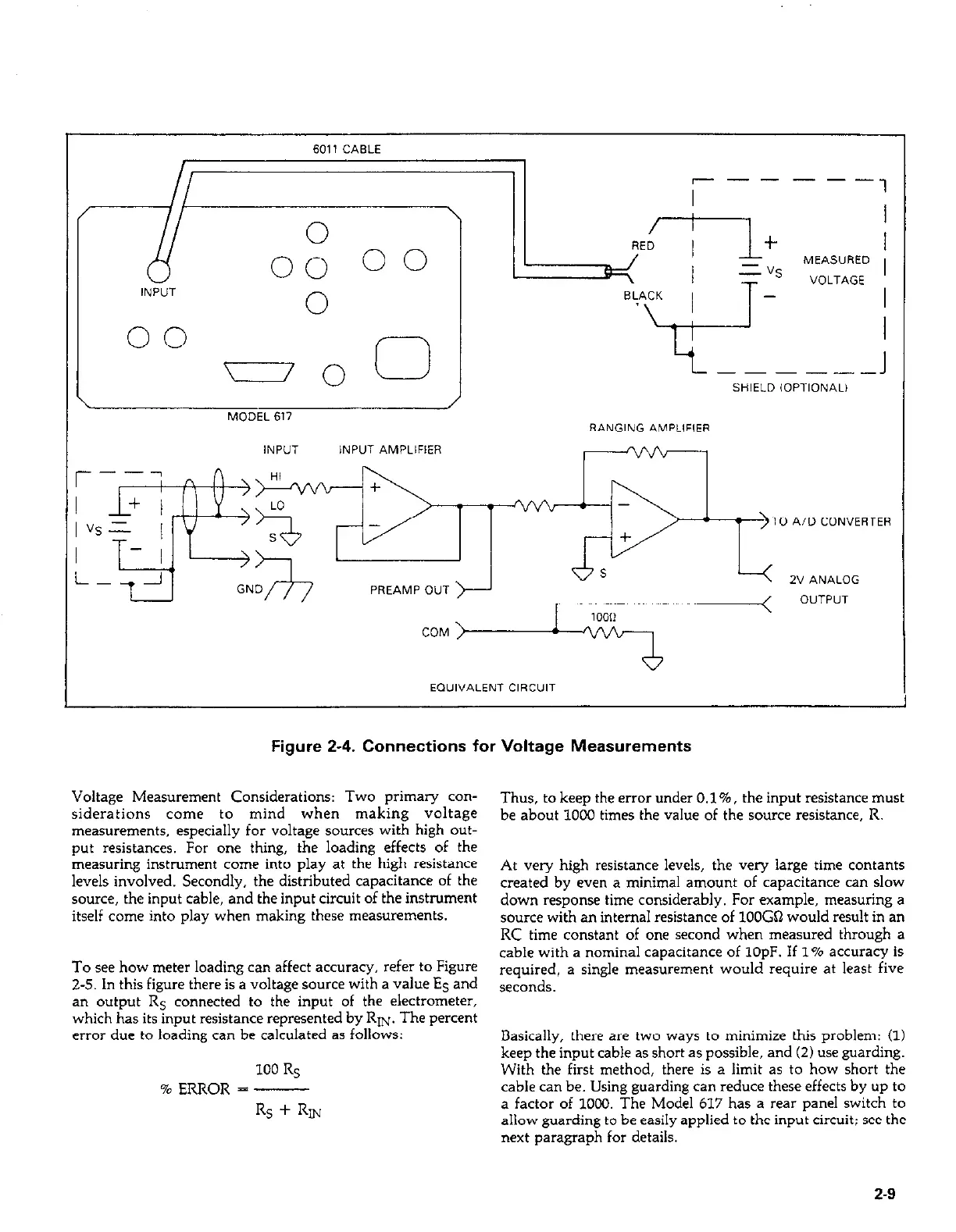
Figure 2-4. Connections for Voltage Measurements
Voltage Measurement Considerations: Two primary con-
siderations come to mind when making voltage
measurements. especially for voltage sources with high out-
put resistances. For one thing, the loading effects of the
measuring instrument come into play at the high resistance
levels involved. Secondly, the distributed capacitance of the
source, the input cable, and the input circuit of the instrument
itself come into play when making these measurements.
To see how meter loading can affect accuracy, refer to Figure
2-5. In this figure there is a voltage source with a value ES and
an output RS connected to the input of the electrometer,
which has its input resistance represented by RIN. The percent
error due to loading can be calculated as follows:
100 RS
% ERROR = -
Rs + RIN
Thus, to keep the error under 0.1%. the input resistance must
be about 1000 times the value of the source resistance. R.
At very high resistance levels, the very large time contants
created by even a minimal amount of capacitance can slow
down response time considerably. For example, measuring a
wurce with an internal resistance of 1OOGQ would result in an
RC time constant of one second when measured through a
cable with a nominal capacitance of 1OpF. If 1% accuracy is
required, a single measurement would require at least five
seconds.
Basically, there are two ways to minimize this problem: (1)
keep the input cable as short as possible, and (2) use guarding.
With the first method, there is a limit as to how short the
cable can be. Using guarding can reduce these effects by up to
a factor of 1000. The Model 617 has a rear panel switch to
allow guarding to be easily applied to the input circuit: see the
next paragraph for details.
2-9
 Loading...


