CALIBRATION USING MODEL 263 CALIBRATOR/SOURCE
INTRODUCTION
The following paragraphs provide detailed procedures to
calibrate the Model 617 using the Model 263 Calibrator/
Source. Most of the calibration procedures are digital in
nature and can be done from the front panel or over the
IEEE-488 bus.
To calibrate the instrument from the front panel, perform
the following procedures, omitting paragraph “IEEE-488
Bus Digital Calibration”. To calibrate the Model 617 over
the IEEE-488 bus, perform the following procedures, omit-
ting paragraph “Front Panel Digital Calibration’:
Calibration Jumper
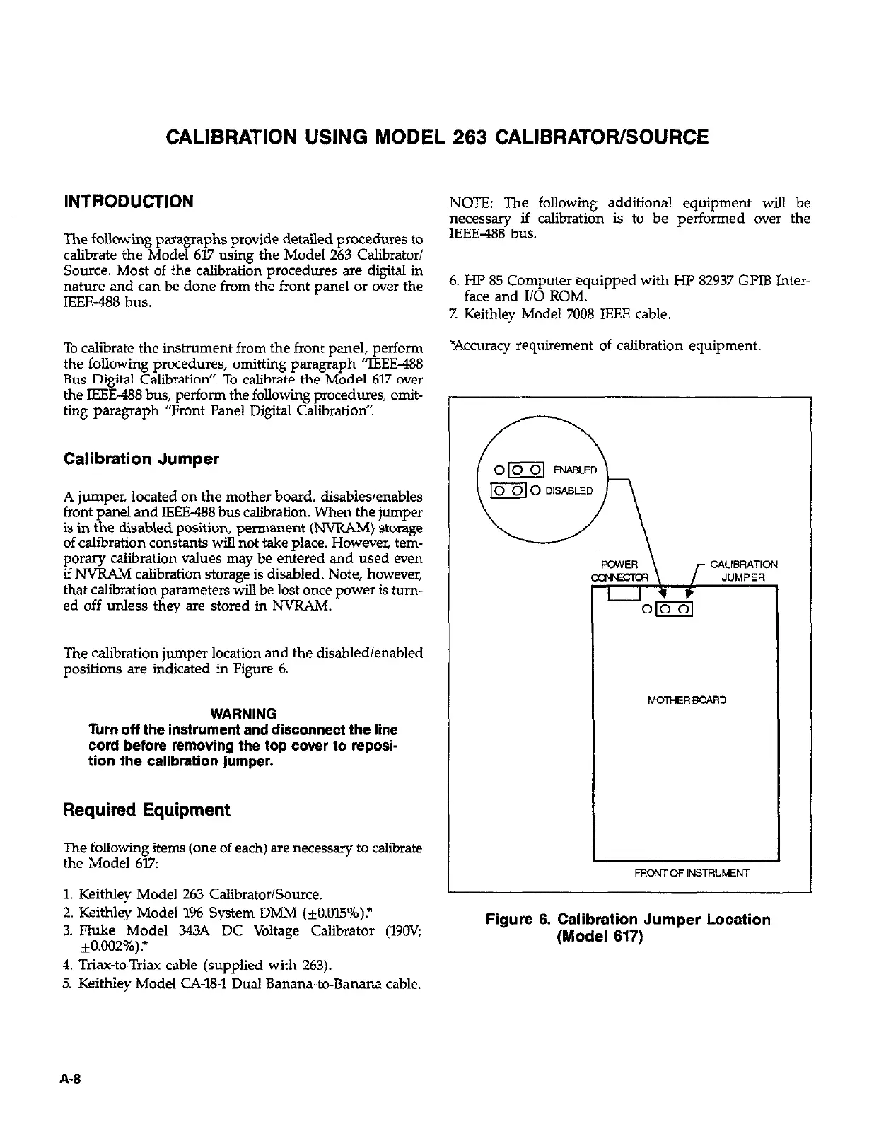
A jumper, located on the mother board, disables/enables
front panel and IEEE-488 bus calibration. When the jumper
is in the disabled position, permanent (NVRAM) storage
of calibration constants will not take place. However, tem-
porary calibration values may be entered and used even
if NVRAM calibration storage is disabled. Note, however,
that calibration parameters will be lost once power is turn-
ed off unless they are stored in NVRAM.
The calibration jumper location and the disabled/enabled
positions are indicated in Figure 6.
WARNING
Turn off the instrument and disconnect the line
cord before removing the top cover to reposi-
tion the calibration jumper.
Required Equipment
The following items (one of each) are necessary to calibrate
the Model 617:
1. Keithley Model 263 Calibrator/Source.
2. Keithley Model 196 System DMM (+O.OlS%).*
3. Fluke Model 343A DC Voltage Calibrator (190V;
*0.002%)?
4. Triaw-to-Triax cable (supplied with 263).
5. Keithley Model CA-W1 Dual Banana-to-Banana cable.
NOTE: The following additional equipment will be
necessary if calibration is to be performed over the
IEEE-488 bus.
6. HP 85 Computer equipped with HP 82937 GI’IB Inter-
face and Ii0 ROM.
7. Keithley Model 7008 IEEE cable.
*Accuracy requirement of calibration equipment
MOTHERBOARD
Figure 6. Calibration Jumper Location
(Model 617)
A-8
 Loading...


