9 SHOCK ABSORBER, SWINGARM 53
200268-10
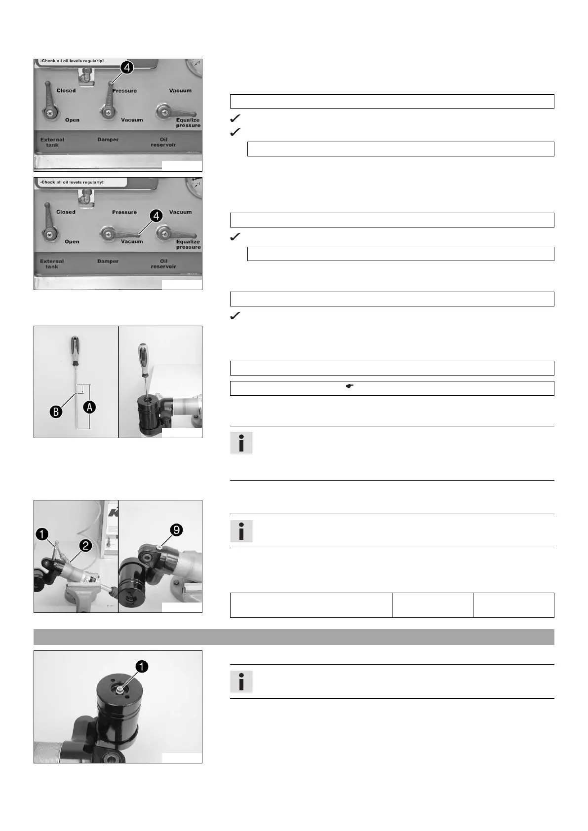
– When the pressure gauge reaches the specified value, turn the Damper control
lever 4 to Pressure.
Guideline
0 bar
Oil is pumped into the damper.
The pressure gauge rises to the specified value.
3 bar
200269-10
– When the pressure gauge reaches the specified value, turn the Damper 4 control
lever to Vacuum.
Guideline
3 bar
The pressure gauge falls to the specified value.
0 bar
– When the pressure gauge reaches the specified value, operate the On/Off switch.
Guideline
0 bar
The vacuum pump is switched off.
201284-10
– Slide O-ring B to the end of the special tool by the specified value (distance A
minus specified value).
Guideline
10 mm
Depth micrometer (T107S) ( p. 223)
– Slide the floating piston into the reservoir to the shortened position using the spe-
cial tool.
Info
The floating piston must be positioned at exactly this point when the rod
is fully extended; otherwise, damage will occur during compression of the
shock absorber.
– Remove the special tool.
201283-10
– Remove adapter 1 from connection 2 of the vacuum pump.
Info
Hold the damper so that the filling port is at the highest point.
– Remove the adapter.
– Mount and tighten screw 9.
Guideline
Filling port screw M10x1 14 Nm
(10.3 lbf ft)
9.21 Filling the damper with nitrogen
201282-10
– Screw in screw 1 by approx. 2 rotations but do not tighten.
Info
The piston rod is fully extended.

 Loading...