G1700·G1800·G1900·G2000
WSM.10830
S.l
ENGINE
(2) Cylinder Head and Valves
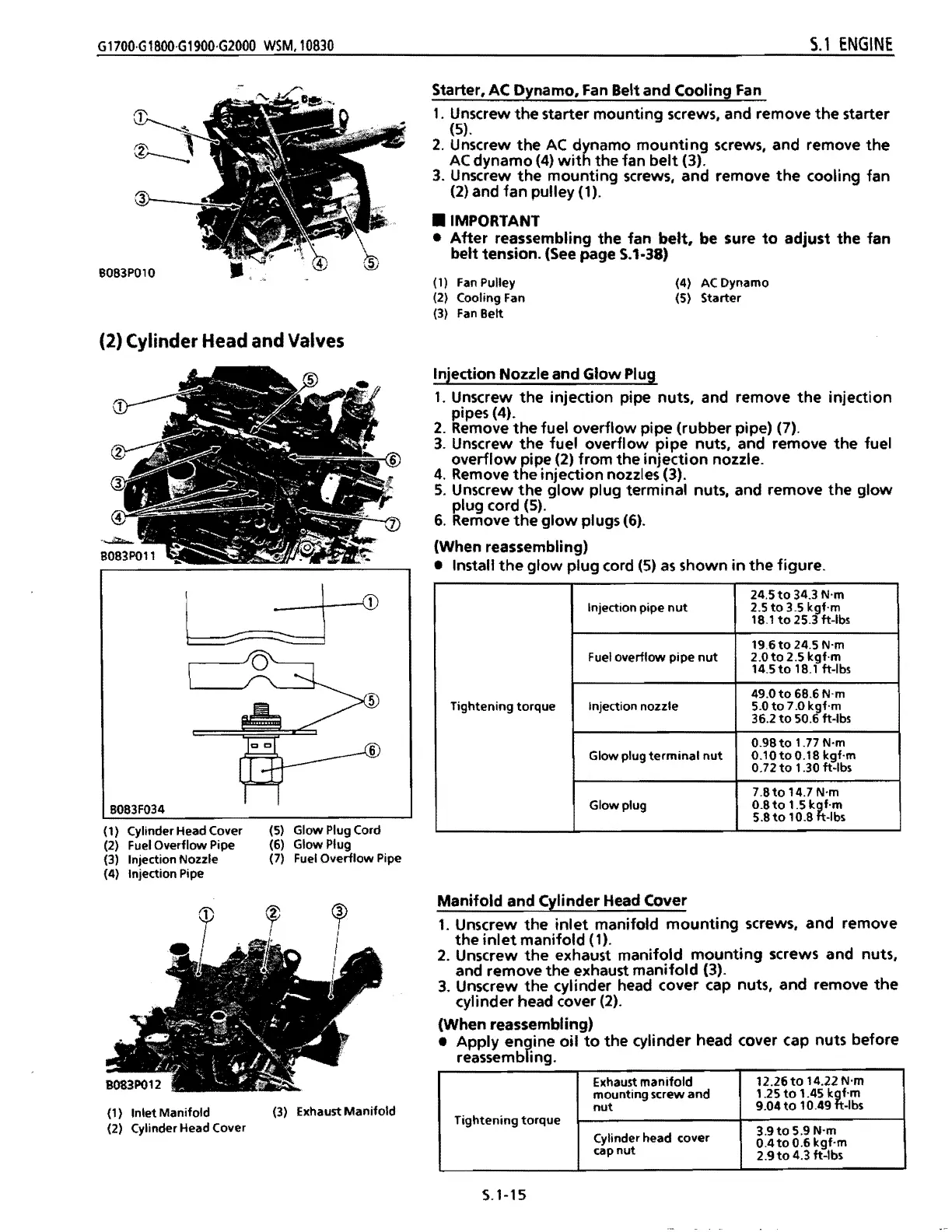
Starter,
AC
Dynamo,
Fan
Belt and Cooling
Fan
1.
Unscrew
the
starter mounting screws, and remove
the
starter
(5).
2.
Unscrew
the
AC
dynamo
mounting
screws, and remove
the
AC
dynamo
(4)
with
the fan
belt
(3).
3.
Unscrew
the
mounting screws, and remove
the
cooling fan
(2)
and fan pulley (1) .
• IMPORTANT
•
After
reassembling the fan
belt,
be sure
to
adjust the fan
belt tension.
(See
page 5.1-38)
(1)
(2)
(3)
Fan
Pulley
Cooling
Fan
Fan
Belt
(4)
(5)
AC
Dynamo
Starter
(5) Glow Plug Cord
(6) Glow Plug
(7)
Fuel
Overflow Pipe
B083
F034
(1) Cylinder Head Cover
(2)
Fuel
Overflow Pipe
(3) Injection Nozzle
(4) Injection Pipe
(1) Inlet Manifold
(3)
Exhaust Manifold
(2) Cylinder Head Cover
Injection Nozzle and Glow Plug
1.
Unscrew
the
injection pipe nuts, and remove
the
injection
pipes (4).
2.
Remove
the
fuel overflow pipe (rubber pipe) (7).
3.
Unscrew
the
fuel overflow pipe nuts, and remove
the
fuel
overflow
pipe (2)
from
the
injection
nozzle.
4.
Remove
the
injection nozzles (3).
S.
Unscrew
the
glow
plug terminal nuts, and remove the
glow
plug cord
(S).
6.
Remove
the
glow
plugs (6).
(When reassembling)
• Install
the
glow
plug cord
(5)
as
shown
in
the
figure.
Tightening torque
Injection pipe
nut
24.5
to
34.3 N'm
2.5
to
3.5 kgf·m
18.1
to
25.3 ft-Ibs
Fuel overflow pipe
nut
19.6
to
24.5 N'm
2.0to
2.5 kgf·m
14.5
to
18.1
ft-Ibs
Injection nozzle
49.0
to
6B.6
N'm
5.0
to
7.0 kgf·m
36.2
to
50.6 ft-Ibs
Glow plug
terminal
nut
0.98
to
1.77 N'm
O.10toO.1B kgf·m
0.72
to
1.30 ft-Ibs
Glow plug
7.8to
14.7 N'm
O.Bto 1.5
k~f.m
5.8
to
10.8
-Ibs
Manifold and Cylinder Head Cover
1.
Unscrew
the
inlet
manifold
mounting
screws, and remove
the
inlet
manifold (1).
2.
Unscrew
the
exhaust manifold
mounting
screws and nuts,
and remove
the
exhaust
manifold
(3).
3.
Unscrew the cylinder head cover cap nuts, and remove
the
cylinder head cover
(2).
(When reassembling)
• Apply engine
oil
to
the cylinder head cover cap nuts before
reassembling.
Exhaust
manifold
12.26to
14.22 N'm
mounting screw
and
1.25
to
1.45
k~f.m
nut
9.04
to
10.49
-Ibs
Tightening
torque
3.9
to
5.9 N'm
Cylinder head cover
0.4
to
0.6
kgf·m
cap
nut
2.9
to
4.3 ft-Ibs
S.1-15
 Loading...