EasyManuals Logo

Kubota G2000 4WS User Manual

Kubota G2000 4WS
392 pages
To Next Page IconTo Next Page
To Previous Page IconTo Previous Page
Page #331 background imageLoading...
Page #331 background image
G1700·G1800·G1900·G2000
WSM.10830
S.8
ELECTRICAL
SYSTEM
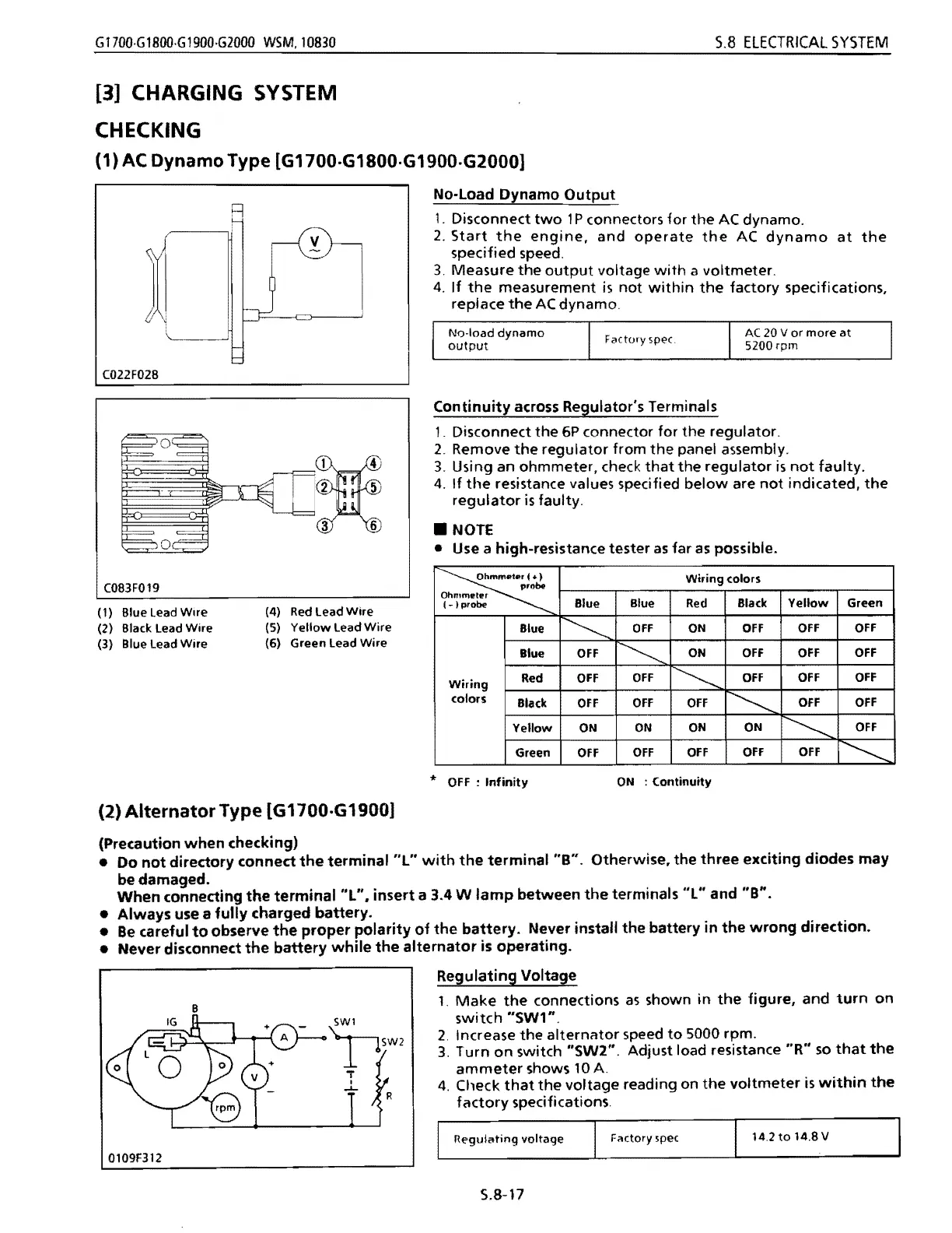
[3] CHARGING SYSTEM
CHECKING
(1) AC
Dynamo
Type
[G1700.G1800.G1900.G2000)
No-Load Dynamo
Output
R
1.
Disconnect
two
1 P connectors for
the
AC
dynamo.
1
2.
Start
the
engine,
and
operate
the
AC
dynamo
at
the
specified speed.
3.
Measure
the
output
voltage
with
a voltmeter.
4.
If
the
measurement
is
not
within
the
factory specifications,
replace
the
AC
dynamo.
No-load
dynamo
AC
20 V
or
more
at
F <'(tory
SPE'C
output
5200
rpm
C022F028
C083F019
(1) Blue Lead
Wire
(2) Black Lead
Wire
(3) Blue
lead
Wire
(2)
Alternator
Type
[61700·G1900]
(Precaution
when
checking)
(4)
Red
lead
Wire
(5)
Yellow
lead
Wire
(6) Green
lead
Wire
Continuity
across Regulator's Terminals
1.
Disconnect
the
6P connector for
the
regulator.
2. Remove
the
regulator
from
the
panel assembly.
3. Using an ohmmeter, check
that
the
regulator
is
not
faulty.
4.
If
the
resistance values specified
below
are
not
indicated,
the
regulator
is
faulty
.
NOTE
Use a high-resistance tester
as
far
as
possible.
~
probe
Ohmmeter
(-
I
probe
Wiring
(olors
Blue
Blue
Red
Black
Yellow
Green
Wiring
colors
Blue
~
OFF
ON
OFF
OFF
OFF
Blue
OFF
~
ON
OFF
OfF
OFF
Red
OFF
OFF
~
OFF
OFF
OFf
Black
OFF
OFF OFF
~
OFF
OFF
Yellow
ON
ON
ON
ON
~
OFF
Green
OFF
OFF
OFF
OFF OFF
~
*
OFF:
Infinity
ON
:
Continuity
Do
not
directory
connect
the
terminal
"L"
with
the
terminal
"B".
Otherwise.
the
three
exciting
diodes
may
be damaged.
When
connecting
the
terminal
"L".
insert
a 3.4 W
lamp
between
the
terminals
"L"
and
"B".
Always
use a
fully
charged
battery.
Be
careful
to
observe
the
proper
polarity
of
the
battery.
Never install
the
battery
in
the
wrong
direction.
Never disconnect
the
battery
while
the
alternator
is
operating.
Regulating Voltage
1.
Make
the
connections
as
shown
in
the
figure,
and
turn
on
B
switch
"SW1".
2.
Increase
the
alternator
speed
to
5000 rpm.
3.
Turn
on
switch
"SW2".
Adjust load resistance
"R"
so
that
the
ammeter
shows
10
A.
4.
Check
that
the
voltage reading on
the
voltmeter
is
within
the
factory
specifications.
R€'gulating
voltage
Filctory spec
14.2
to
14.8 V
0109F312
5.8-17

Table of Contents

Questions and Answers:

Question and Answer IconNeed help?

Do you have a question about the Kubota G2000 4WS and is the answer not in the manual?

Kubota G2000 4WS Specifications

General IconGeneral
BrandKubota
ModelG2000 4WS
CategoryTractor
LanguageEnglish

Related product manuals