5.2
TRANSMISSION
AND
REAR
AXLE
G1700·G1800·G1900·G2000 WSM,10832
DISASSEMBLING
AND
ASSEMBLING
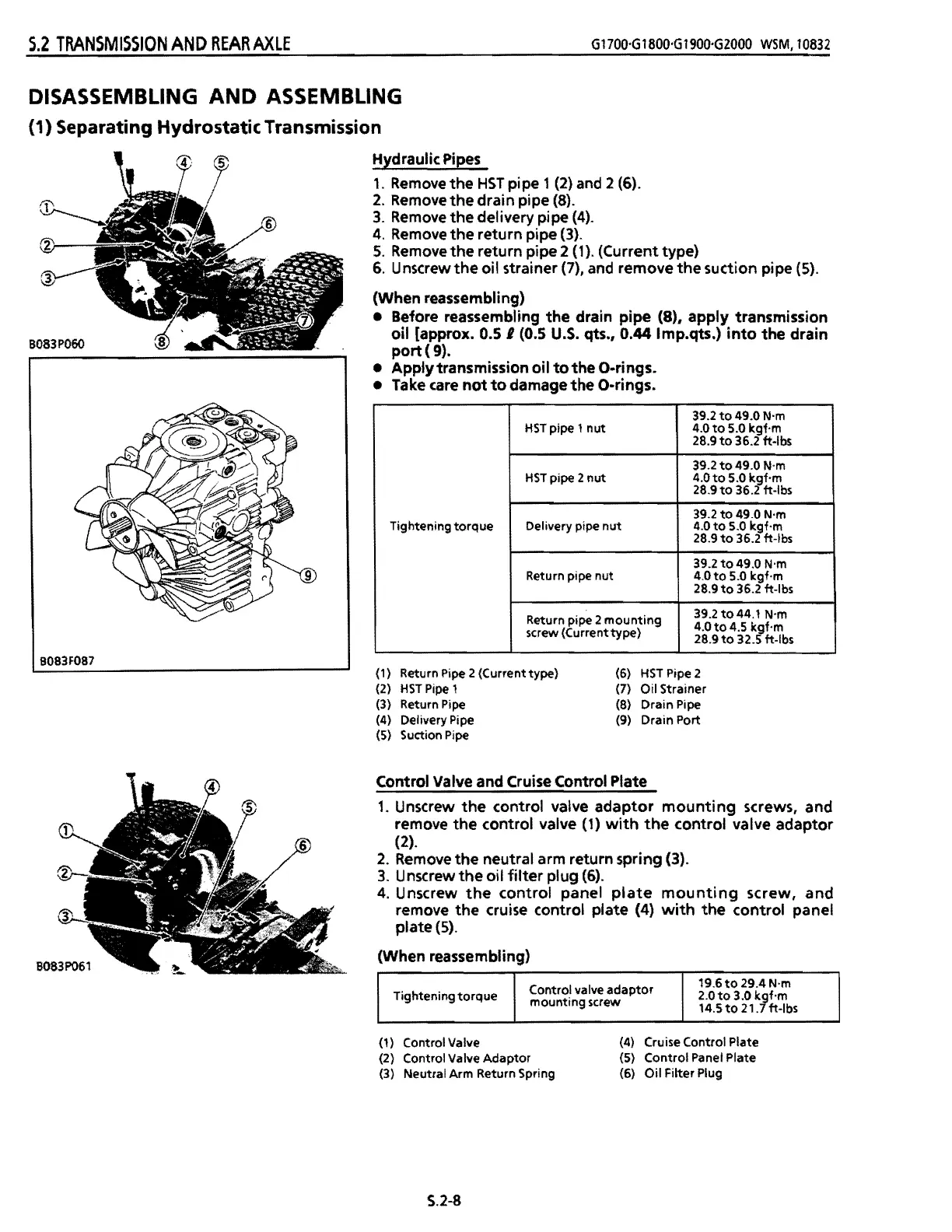
{1} Separating Hydrostatic Transmission
Hydraulic
Pipes
1.
Remove
the
HST
pipe 1
(2)
and
2
(6).
2.
Remove
the
drain pipe (8).
3.
Remove
the delivery pipe (4).
4.
Remove
the return pipe (3).
5.
Remove
the return pipe 2 (1). (Current type)
6. U nscrew
the
oil strainer (7),
and
remove the suction pipe (5).
(When reassembling)
• Before reassembling the drain pipe
(8), apply transmission
oil [approx.
0.5 I (0.5
U.S.
qts., 0.44 Imp.qts.)
into
the drain
port
(
9).
• Apply transmission oil
to
the O-rings.
• Take
care
not
to
damage the O-rings.
Tightening
torque
HST
pipe 1
nut
39.2
to
49.0 N'm
4.0
to
5.0 kgf·m
28.9
to
36.2 ft-Ibs
HST
pipe 2
nut
39.2
to
49.0 N'm
4.0to
5.0 kgf·m
28.9
to
36.2 ft-Ibs
Delivery pipe
nut
39.2
to
49.0 N'm
4.0
to
5.0 kgf·m
28.9
to
36.2 ft-Ibs
Return pipe nut
39.2
to
49.0 N'm
4.0
to
5.0 kgf·m
2S.9to
36.2 ft-Ibs
Return pipe 2
mounting
screw (Current
type)
39.2to44.1
N'm
4.0
to
4.5 kgf·m
28.9
to
32.5 ft-Ibs
B083F087
(1
)
Return Pipe 2 (Current type)
(6)
HST
Pipe 2
(2)
HST
Pipe
1
(7)
Oil Strainer
(3)
Return
Pipe
(S)
Drain Pipe
(4)
Delivery Pipe
(9)
Drain Port
(5)
Suction Pipe
Control Valve and Cruise Control Plate
1.
Unscrew
the
control valve adaptor
mounting
screws, and
remove the control valve
(1)
with
the
control valve adaptor
(2).
2.
Remove
the neutral arm return spring (3).
3.
Unscrew
the
oil
filter
plug
(6).
4.
Unscrew
the
control panel
plate
mounting
screw, and
remove the cruise control plate (4)
with
the
control panel
plate
(5).
(When reassembling)
Tightening
torque
Control valve
adaptor
mounting screw
19.6
to
29.4 N·m
2.0
to
3.0 kgf·m
14.5
to
21.7 ft-Ibs
(1) Control Valve
(4) Cruise Control Plate
(2) Control Valve
Adaptor
(5) Control Panel Plate
(3) Neutral Arm Return Spring
(6)
Oil
Filter Plug
S.2-8
 Loading...