14.HANDLEBAR/FRONT WHEEL/FRONTBRAKE/
FRONT SHOCK ABSORBER/STEERING STEM
14-28
DINK 50/125
FRONT SHOCK ABSORBER
REMOVAL
Remove the front cover and front fender.
(
refer to the “FRAME CVOERS
REMOVAL/INSTALLATION” section in
the chapter 2
).
Remove the front brake caliper (
refer to the
“
FRONT BRAKE PAD
” section in this
chapter
).
Remove the front wheel (
refer to the
“
FRONT WHEEL
” section in this chapter
).
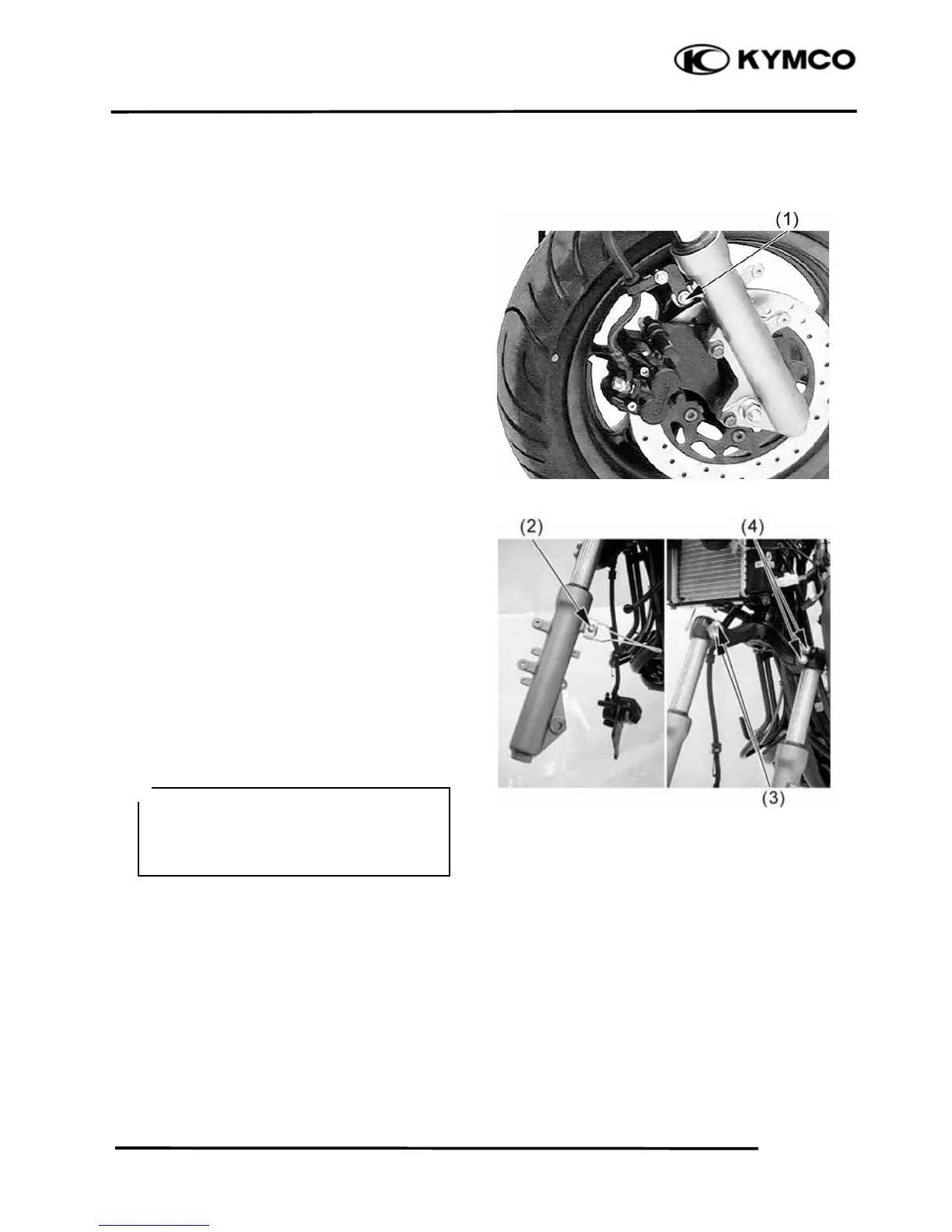
Remove the bolt (1) and then remove the
brake hose guide from right front shock
absorber.
Remove the bolt (2) and then remove the
speedometer cable guide from left front shock
absorber.
Remove the two mounting bolts (3) and then
remove the right front shock absorber.
Remove the two mounting bolts (4) and then
remove the left front shock absorber.
INSTALLATION
Installation is in the reverse order of removal.
INSPECTION
Inspect the following items and replace if
necessary.
•Front shock absorber tube bending, damage
or wear
•Weak front shock absorber spring
•Damper and damper rod bending
•Oil seal damage or wear
Tighten the shock absorber mounting
bolt to the specified torque.
Torque: 3.2 kgf-m (32 N-m, 23 lbf-ft)
*
 Loading...