19. LIGHTS/METERS/SWITCHES
19-6
DINK 50/125
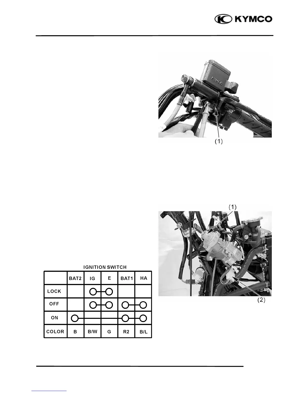
BRAKE LIGHT SWITCH
Remove the upper handlebar cover (refer to
the “FRAME COVERS
REMOVAL/INSTALLATION” section in
the chapter 2).
Disconnect front or rear light switch
connectors and check for continuity
between the switch terminals (1).
There should be continuity with the front or
rear brake lever squeezed, and there should
be no continuity with the front or rear brake
lever is released.
IGNITION SWITCH
INSPECTION
Remove the front cover (refer to the
“FRAME COVERS
REMOVAL/INSTALLATION” section in
the chapter 2).
Disconnect the ignition switch connector (2)
and check the ignition switch (1) for
continuity at the switch side connector
terminals.
Continuity should exist between the color
code wires as follows:
 Loading...