3. INSPECTION/ADJUSTMENT
3-16
DINK50/125
VALVE CLEARANCE(DINK 50)
Remove the met-in box and center cover.
Remove cylinder head cover.
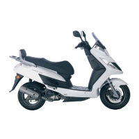
Turn the A.C. generator flywheel to the top
dead center (TDC) on the compression stroke
so that the “T” mark on the flywheel aligns
with the index mark on the right crankcase.
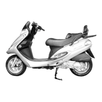
The time marks on the cam sprocket must be
flush with the cylinder head surface and
round hole on the cam sprocket must be
facing up as shown.
If the round hole on the cam sprocket are
facing down, turn the crankshaft clockwise
one full turn and realign the timing marks
with the cylinder head surface so it is facing
up.
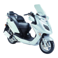
Insert a thickness gauge between the valve
stem end and the adjusting screw on the
rocker arm.
If the clearance is out of specification, bring
it into the specified range.
Valve Clearance: IN: 0.04~0.06mm
EX: 0.04~0.06mm
Loosen the lock nut and adjust by turning the
adjusting nut
Valve Adjuster E036
• Inspect and adjust valve clearance
while the engine is cold (below 35℃).
*
Special
• Check the valve clearance again afte
 Loading...