EasyManua.ls Logo

Lenze I51AE175B User Manual

Lenze I51AE175B
487 pages
To Next Page IconTo Next Page
To Previous Page IconTo Previous Page
Page #402 background imageLoading...
Page #402 background image
13.11 Sequencer control funcons
The following funcons serve to control the sequencer. 4Sequencer ^ 325
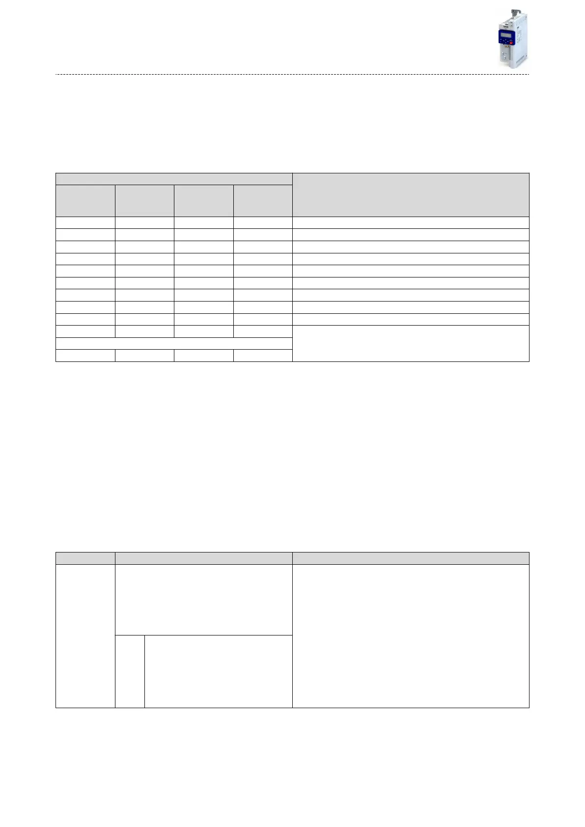
Select sequence
A sequence is selected in a binary-coded fashion via the triggers assigned to the four funcons
"Select sequence (bit 0)" ... " Select sequence (bit 3)" in compliance with the following truth
table:
Select sequence Selecon
Bit 3
0x2631:053
(P400.53)
Bit 2
0x2631:052
(P400.52)
Bit 1
0x2631:051
(P400.51)
Bit 0
0x2631:050
(P400.50)
FALSE FALSE FALSE FALSE No sequence selected
FALSE FALSE FALSE TRUE Sequence 1
FALSE FALSE TRUE FALSE Sequence 2
FALSE FALSE TRUE TRUE Sequence 3
FALSE TRUE FALSE FALSE Sequence 4
FALSE TRUE FALSE TRUE Sequence 5
FALSE TRUE TRUE FALSE Sequence 6
FALSE TRUE TRUE TRUE Sequence 7
TRUE FALSE FALSE FALSE Sequence 8
TRUE FALSE FALSE TRUE Invalid selecon
...
TRUE TRUE TRUE TRUE
Start sequence
The selected sequence is not started automacally. For starng the sequence, two funcons
are available:
0x2631:030 (P400.30): Run/abort sequence (status-controlled start)
0x2631:031 (P400.31): Start sequence (edge-controlled start)
Further control funcons
The following funcons serve to control the started sequence:
0x2631:032 (P400.32): Next sequence step
0x2631:033 (P400.33): Pause sequence
0x2631:034 (P400.34): Suspend sequence
0x2631:035 (P400.35): Stop sequence
0x2631:036 (P400.36): Abort sequence
For controlling the sequencer via network, the sequencer control funcons can also be
assigned to the NetWordIN1 data word 0x4008:001 (P590.01).
Parameter Name / value range / [default seng] Info
0x2631:030
(P400.30)
Funcon list: Run/abort sequence
(Funcon list: Seq: Run/abort)
Seng can only be changed if the inverter is inhibi-
ted.
From version 03.00
For further possible sengs, see parameter
0x2631:001 (P400.01). ^ 351
Assignment of a trigger for the "Run/abort sequence" funcon.
Trigger = TRUE: Start selected sequence.
Trigger = FALSE: Abort sequence.
Notes:
The assigned trigger must remain set to TRUE for the duraon of the
sequence.
If the trigger bit is reset to FALSE, the sequence is aborted. In this
case, the standard setpoint or the setpoint source selected via set-
point change-over is acve again.
A sequence is selected in a binary-coded fashion via the trigger
assigned to the four funcons "Select sequence (bit 0)" 0x2631:050
(P400.50) ... "Select sequence (bit 3)" 0x2631:053 (P400.53).
For an edge-controlled start, the funcon "Start sequence"
0x2631:031 (P400.31) is oponally available.
0 Not connected
Flexible I/O conguraon
Sequencer control funcons
402

Table of Contents

Other manuals for Lenze I51AE175B

Question and Answer IconNeed help?

Do you have a question about the Lenze I51AE175B and is the answer not in the manual?

Lenze I51AE175B Specifications

General IconGeneral
BrandLenze
ModelI51AE175B
CategoryInverter
LanguageEnglish

Summary

Safety instructions

Basic safety measures

Guidelines for preventing personal injury and material damage, including product usage and handling.

Residual hazards

Identifies potential hazards like electrostatic discharge, electrical voltage, hot surfaces, and motor residual movement.

Application as directed

Specifies intended use, compliance with directives, and requirements for personnel qualifications.

Electrical installation

Mains connection

Details on connecting the inverter to single-phase and three-phase power supplies.

Commissioning

Important notes

Critical warnings about incorrect wiring and settings during commissioning.

Parameter setting

Explains how to adapt the inverter to the drive task by changing parameters.

Diagnostics and fault elimination

Error handling

Explains error types, configuration, reset procedures, and keypad error messages.

Basic setting

Mains voltage

Details on setting the rated mains voltage for proper inverter operation.

Motor control

Motor data

Defines motor parameters that characterize its electrical behavior.

Motor control selection

Supports various modes like V/f, sensorless vector, and synchronous motor control.

Motor protection

Includes monitoring functions for overload, current limits, phase failure, and speed.

Configuring the network

Configuring the process controller

Basic process controller settings

Covers PID controller basic settings, including operating mode and analog input configuration.

Additional functions

Device Commands

Commands for organizational functions like saving, loading, and resetting parameters.

DC braking

Explains DC braking function for motor control, including automatic and manual activation.

Access protection

Covers write access protection via keypad and EASY Starter for parameter security.

Holding brake control

Manages the holding brake for low-wear control, including automatic and manual release.

Mains failure control

Allows deceleration of the motor using rotational energy during power failure.

Sequencer

Segment configuration

Details the configuration of up to 8 segments and one end segment for sequences.

Sequence configuration

Describes how to configure 8 sequences, each with 16 steps.

Sequencer basic settings

Covers enabling the sequencer, setting operating modes, end modes, and start modes.

Flexible I/O configuration

Start / stop motor

Details configuration of triggers for basic motor control functions like start, stop, and reverse.

Appendix

Error codes

Lists and explains all inverter error messages, including causes and remedies.

Related product manuals