13.6 Releasing holding brake manually
The "Release holding brake" funcon serves to release the holding brake immediately. Brake
applicaon me and brake opening me as well as the condions for the automac operaon
are not eecve.
Precondions
•
Observe seng and applicaon notes in the "Holding brake control" chapter! ^ 300
•
The brake mode "Automac [0]" or "Manual [1]" must be set in 0x2820:001 (P712.01).
•
The "Release holding brake [115]" trigger has to be assigned to a digital output or, in the
simplest case, to the relay which then switches the brake supply.
Details
Detailed informaon about the funcon and conguraon of the holding brake control can be
found in the "Holding brake control" chapter. ^ 300
Parameter Name / value range / [default seng] Info
0x2631:049
(P400.49)
Funcon list: Release holding brake
(Funcon list: Release brake)
•
Seng can only be changed if the inverter is inhibi-
ted.
•
For further possible sengs, see parameter
0x2631:001 (P400.01). ^ 351
Assignment of a trigger for the "Release holding brake" funcon.
Trigger = TRUE: Release holding brake (immediately).
Trigger = FALSE: no acon.
Notes:
•
Funcon is only executed if the brake mode 0x2820:001 (P712.01) is
set to "Automac [0]" or "Manual [1]".
CAUTION!
•
The manually triggered "Release holding brake" command has a direct
impact on the "Release holding brake [115]" trigger. Thus, the holding
brake can be manually released if the power secon is switched o!
•
The responsibility for a manual release of the holding brake has the
external trigger source for the "Release holding brake" command!
0 Not connected
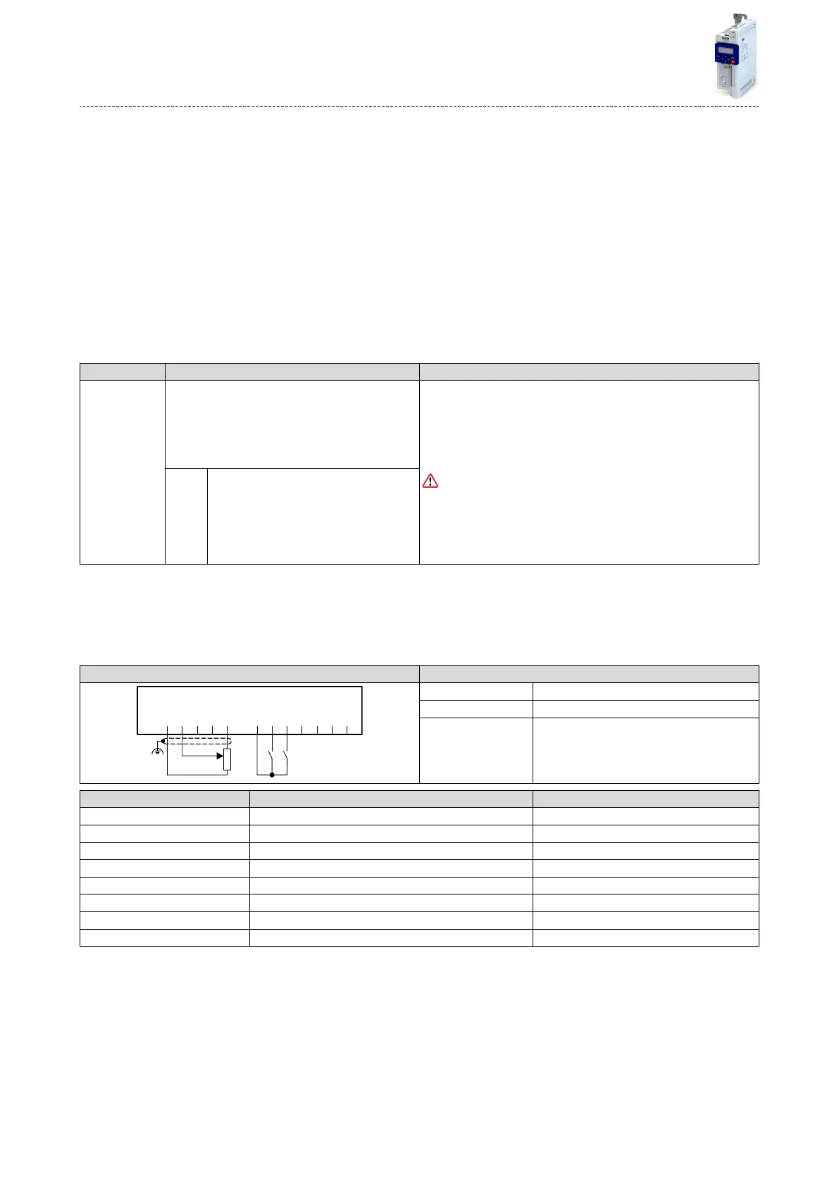
Example for operang mode
•
Switch S1 starts the motor in forward direcon of rotaon. Switch S1 in the inial posion
stops the motor again.
•
Switch S2 releases the holding brake. For this purpose, in this example, trigger "Release
holding brake [115]" is assigned to the relay that switches the brake supply.
Connecon plan funcon
GND
AI1
AI2
AO1
10V
24V
DI1
DI2
DI3
DI4
DI5
DO1
X3
S1 S2
1k ...10k
0 ... 10 V
R1
Potenometer R1 Frequency setpoint selecon
Switch S1 Run
Switch S2 Release holding brake
Parameter Name Seng for this example
0x2631:001 (P400.01) Enable inverter Constant TRUE [1]
0x2631:002 (P400.02) Run Digital input 1 [11]
0x2631:004 (P400.04) Reset fault Not connected [0]
0x2631:049 (P400.49) Release holding brake Digital input 2 [12]
0x2634:001 (P420.01) Relay Release holding brake [115]
0x2824 (P200.00) Control selecon Flexible I/O conguraon [0]
0x2838:003 (P203.03) Stop method Standard ramp [1]
0x2860:001 (P201.01) Frequency control: Default setpoint source Analog input 1 [2]
Flexible I/O conguraon
Releasing holding brake manually
388
 Loading...


