4
HARDWARE SPECIFICATIONS OF THE CPU MODULE
4.2 Basic Model QCPU
4.2.1 Part Names
4 - 21
1
OVERVIEW
2
SYSTEM
CONFIGURATION
3
GENERAL
SPECIFICATIONS
4
HARDWARE
SPECIFICATIONS OF
THE CPU MODULE
5
POWER SUPPLY
MODULE
6
BASE UNIT AND
EXTENSION CABLE
7
MEMORY CARD AND
BATTERY
8
CPU MODULE START-
UP PROCEDURES
4.2 Basic Model QCPU
4.2.1 Part Names
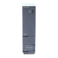
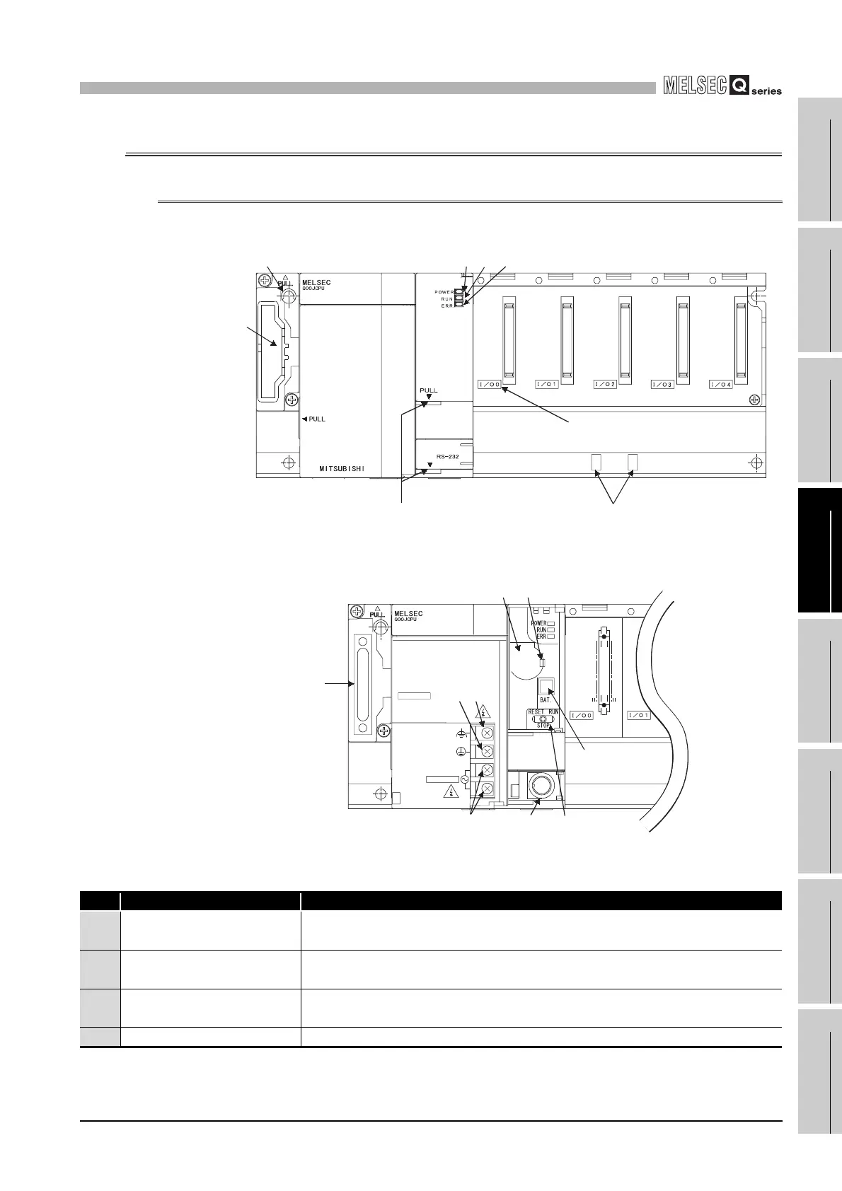
(1) Q00JCPU
Diagram 4.1 Front face
Diagram 4.2 With front cover open
Table4.6 Part Names
No. Name Application
1) Base mounting hole
Pear-shaped hole for mounting the unit to a panel such as a control box. (For M4
screw)
2) Cover
Protective cover for extension cable connector. Remove this cover when connecting
an extension base unit.
3) Extension cable connector
Connector for transfer of signals to/from the extension base unit. Connect an
extension cable.
4) POWER LED Power indicator LED for 5VDC. Lights up in green when 5VDC is output normally.
4) 5) 6)
1)
2)
7)
OUT
8)
When opening the cover, put your
finger here.
3)
OUT
9)10)
11)
14)
16)15)
12) 13)
(FG)
(LG)
N
L
100-240VAC
INPUT
100-240VAC
INPUT
100-240VAC
INPUT
50/60Hz 105VA
OUTPUT
5VDC3A
 Loading...