6
BASE UNIT AND EXTENSION CABLE
6.1 Base Unit
6.1.1 Specification Table
6 - 1
1
OVERVIEW
2
SYSTEM
CONFIGURATION
3
GENERAL
SPECIFICATIONS
4
HARDWARE
SPECIFICATIONS OF
THE CPU MODULE
5
POWER SUPPLY
MODULE
6
BASE UNIT AND
EXTENSION CABLE
7
MEMORY CARD AND
BATTERY
8
CPU MODULE START-
UP PROCEDURES
CHAPTER6 BASE UNIT AND EXTENSION CABLE
This chapter describes the specifications of the extension cables for the
base units (the main base unit, slim type main base unit, redundant power main base unit,
extension base unit, redundant power extension base unit and redundant type extension
base unit) used in the programmable controller system and the specification standards of
the extension base unit.
6.1 Base Unit
6.1.1 Specification Table
The base unit is a unit to which the CPU module, power supply module, I/O module and/or
intelligent function module are installed.
Section 6.1.1 to Section 6.1.4 provide the specifications and other information on the base
unit.
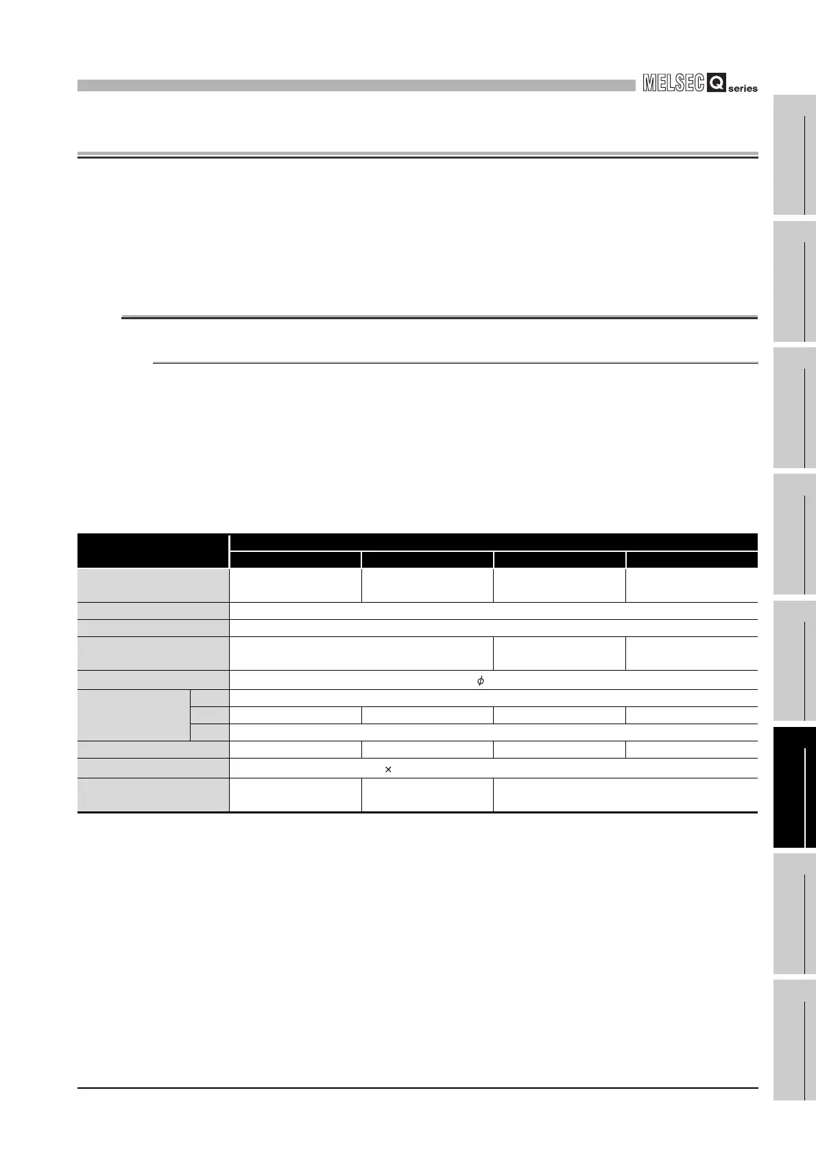
(1) Main base unit
* 1: The 5 base mounting screws are included with the Q38B and Q312B that have 5 base mounting
holes.
Table6.1 Main base unit specifications
Item
Type
Q33B Q35B Q38B Q312B
Number of I/O modules
installed
35812
Possibility of extension Extendable
Applicable module Q series modules
5 VDC internal current
consumption
0.11A 0.12A 0.13A
Mounting hole size
M4 screw hole or 4.5 hole (for M4 screw)
External dimensions
H 98mm (3.86inch)
W 189mm (7.44inch) 245mm (9.65inch) 328mm (12.92inch) 439mm (17.28inch)
D 44.1mm (1.74inch)
Weight 0.21kg 0.27kg 0.36kg 0.47kg
Attachment
Mounting screw M4 14 4 pieces*
1
(DIN rail mounting adapter to be sold separately)
DIN rail mounting adapter
type
Q6DIN3 Q6DIN2 Q6DIN1
 Loading...