10
LOADING AND INSTALLATION
10.4 How to Set Stage Numbers for the Extension Base Unit
10 - 31
9
EMC AND LOW
VOLTAGE
DIRECTIVES
10
LOADING AND
INSTALLATION
11
MAINTENANCE AND
INSPECTION
12
TROUBLESHOOTING APPENDICES INDEX
10.4 How to Set Stage Numbers for the Extension Base Unit
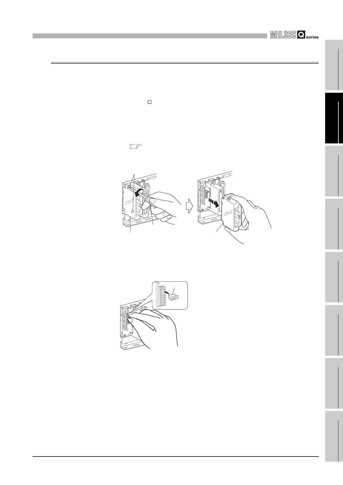
When using two or more extension base units, their stage numbers must be set with their
stage number setting connectors.
*1
(The number of extension stages is set to 1 by factory default.)
* 1: Since the Q6 WRB is fixed to the first extension stage, extension stage No. setting is not
required.
Make this setting in the following procedure.
1) The stage number setting connector of the extension base unit is located
under the IN side base cover. (Setting of the extension number setting connec-
tor ( Section 6.1.3))
First, loosen the upper and lower screws in the IN side base cover and remove
the base cover from the extension base unit.
2) Insert the connector pin in the required stage number location of the connector
(PIN1) existing between the IN and OUT sides of the extension cable
connector.
Diagram 10.29 Removing a base cover
Diagram 10.30 Setting the number of extension stages
Flat blade screwdriver
Base cover
Extension base unit
Fixing screw
Base cover
Connector pin
 Loading...