7
MEMORY CARD AND BATTERY
7.1 Memory Card
7.1.3 The Part Names of the Memory Card
7 - 4
1
OVERVIEW
2
SYSTEM
CONFIGURATION
3
GENERAL
SPECIFICATIONS
4
HARDWARE
SPECIFICATIONS OF
THE CPU MODULE
5
POWER SUPPLY
MODULE
6
BASE UNIT AND
EXTENSION CABLE
7
MEMORY CARD AND
BATTERY
8
CPU MODULE START-
UP PROCEDURES
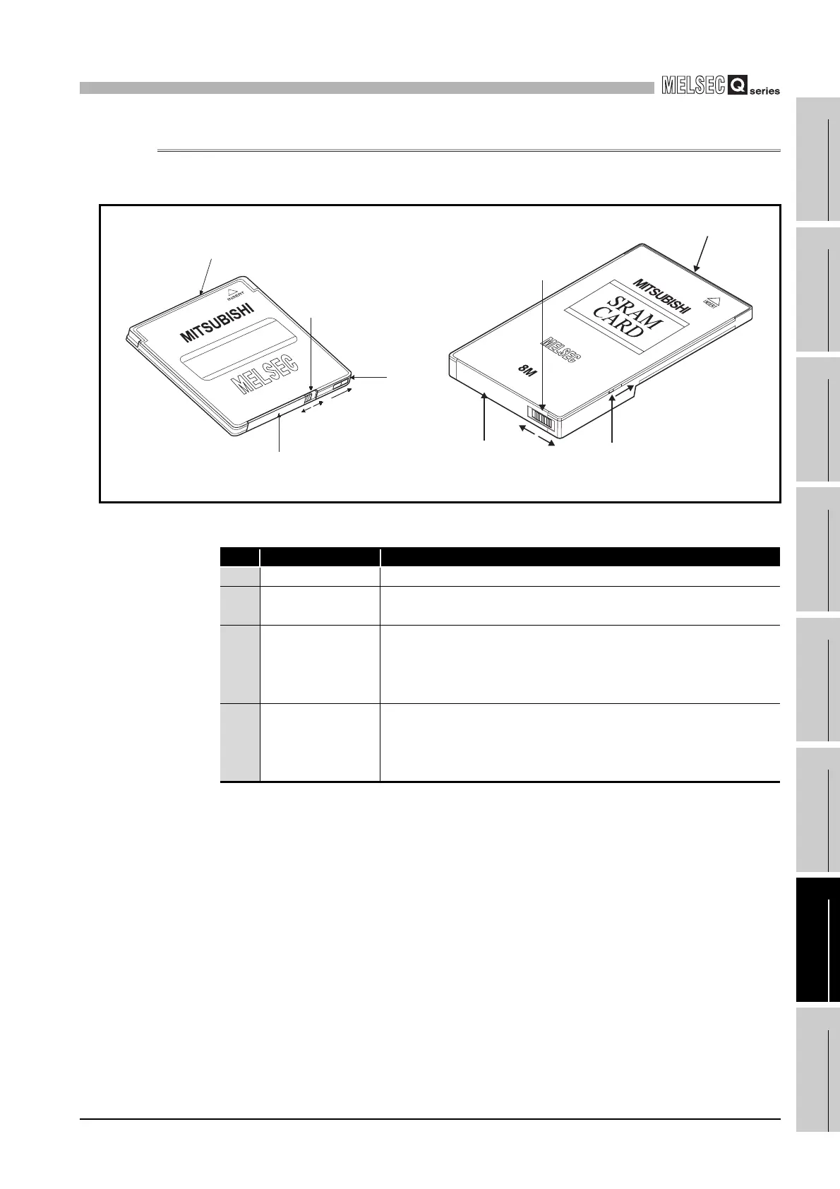
7.1.3 The Part Names of the Memory Card
The part names of the memory card are described below.
* : The battery holder fixing switch is returned automatically from RELEASE to LOCK when the battery
holder is disconnected.
Diagram 7.2 Memory card
Table7.6 Part Names
No. Name Descriptions
1) Connector area Connector area connected to the CPU module
2) Battery holder
Used to set the lithium battery for data backup of the SRAM memory
(SRAM card only)
3)
Battery holder fixing
switch
*
Switch for fixing the battery holder to the memory card. Locked at
LOCK position (write protect switch side)
LOCK: Locked, RELEASE: Unlocked
(SRAM card only)
4) Write protect switch
Used to set write inhibit in the memory. Set to OFF by factory default.
(SRAM card and Flash card only)
ON : Data write inhibited
OFF: Data write enabled
Write protect ON
2)
1)
4)
3)
"LOCK"
"RELEASE"
2)
3)
"LOCK"
Write protect ON
"RELEASE"
1)
4)
 Loading...