12 - 24
12.2 Troubleshooting
12.2.19 Flowchart for when UNIT VERIFY ERR. occurs
12
TROUBLESHOOTING
12.2.19 Flowchart for when UNIT VERIFY ERR. occurs
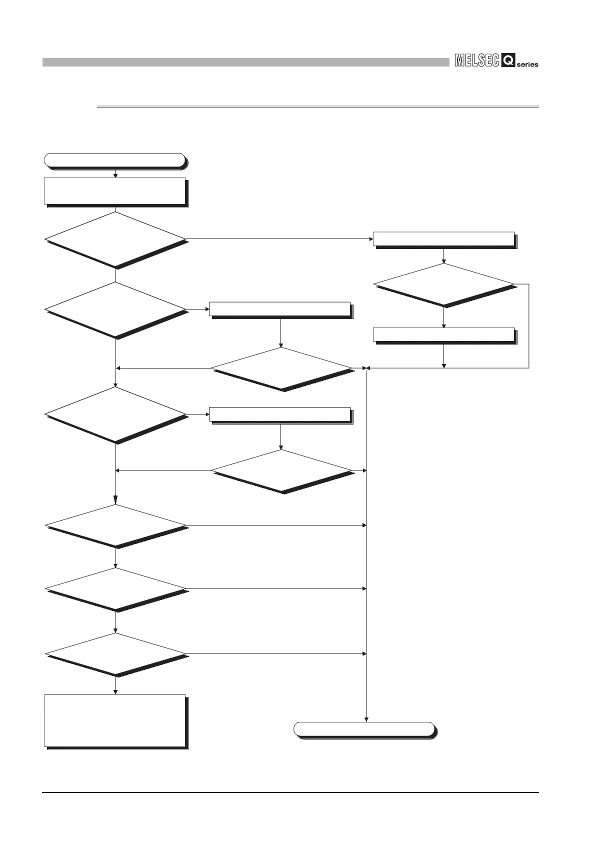
The following shows the flowchart for when UNIT VERIFY ERR. occurs at programmable
controller power-on or during operation.
Diagram 12.16 Flowchart for when UNIT VERIFY ERR. occurs
Replace the
corresponding module.
Has the "ERR."
LED turned off?
Has the "ERR."
LED turned off?
Has the "ERR."
LED turned off?
Connect the extension cable properly.
Replace the corresponding module.
Reset the CPU module.
Replace the CPU
module.
Error detection
Error detection
Error detection
Normal operation
Normal operation
Normal operation
Replace the
applicable base unit.
Check the slot where error occurred
with the GX Developer.
NO
NO
NO
NO
NO
NO
YES
YES
YES
YES
YES
YES
Completed
Hardware fault
Please consult your local Mitsubishi
service center or representative,
explaining a detailed description of
the problem.
Is the module
of the applicable slot
mounted properly?
Are all the
extension cables of
the base unit connected
properly?
Has
the module on
the corresponding slot been
removed/mounted during
operation?
The UNIT VERIFY ERR. has occured.
Mounted the module properly.
Please consult your local nearest
Mitsubishi or representative,
explaining a detailed description of
the problem.
 Loading...