10
LOADING AND INSTALLATION
10.6 Wiring
10.6.2 Connecting to the power supply module
10 - 41
9
EMC AND LOW
VOLTAGE
DIRECTIVES
10
LOADING AND
INSTALLATION
11
MAINTENANCE AND
INSPECTION
12
TROUBLESHOOTING APPENDICES INDEX
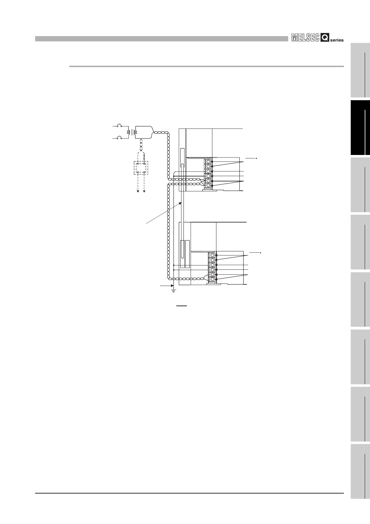
10.6.2 Connecting to the power supply module
The following diagram shows the wiring example of power lines, grounding lines, etc. to
the main and extension base units.
(1) Singular power supply system
* 1: The operation of the ERR terminal is as fllows.
<When the power supply module is mounted on the main base unit>
The terminal turns OFF (opens) when the AC power is not input, a CPU module stop error
(including a reset) occurs, or the fuse of the power supply module is blown.
<When the power supply module is mounted on the extension base unit>
The terminal is always OFF (open).
Diagram 10.42 Single power supply system wiring example
AC
AC
DC
100/110VAC
24VDC
Q61P-A1
Q61P-A1 I/O module
100VAC
FG
LG
INPUT
100-120VAC
FG
LG
INPUT
100-120VAC
Fuse
Connect to 24VDC
terminals of I/O module
that requires 24VDC
internally.
Extension cable
Ground wire
Grounding
Main base unit
(Q38B)
CPU module
Extension base unit
(Q68B)
ERR
1
ERR
1
 Loading...