9 - 4
9.1 Requirements for Conformance to EMC Directive
9.1.3 Cables
9
EMC AND LOW VOLTAGE DIRECTIVES
9.1.3 Cables
The cables extracted from the control panel contain a high frequency noise component.
On the outside of the control panel, therefore, they serve as antennas to emit noise. To
prevent noise emission, use shielded cables for the cables which are connected to the I/O
modules and intelligent function modules and may be extracted to the outside of the
control panel.
The use of a shielded cable also increases noise resistance.
The signal lines (including common line) of the programmable controller, which are
connected to I/O modules, intelligent function modules and/or extension cables, have
noise durability in the condition of grounding their shields by using the shielded cables. If a
shielded cable is not used or not grounded correctly, the noise resistance will not meet the
specified requirements.
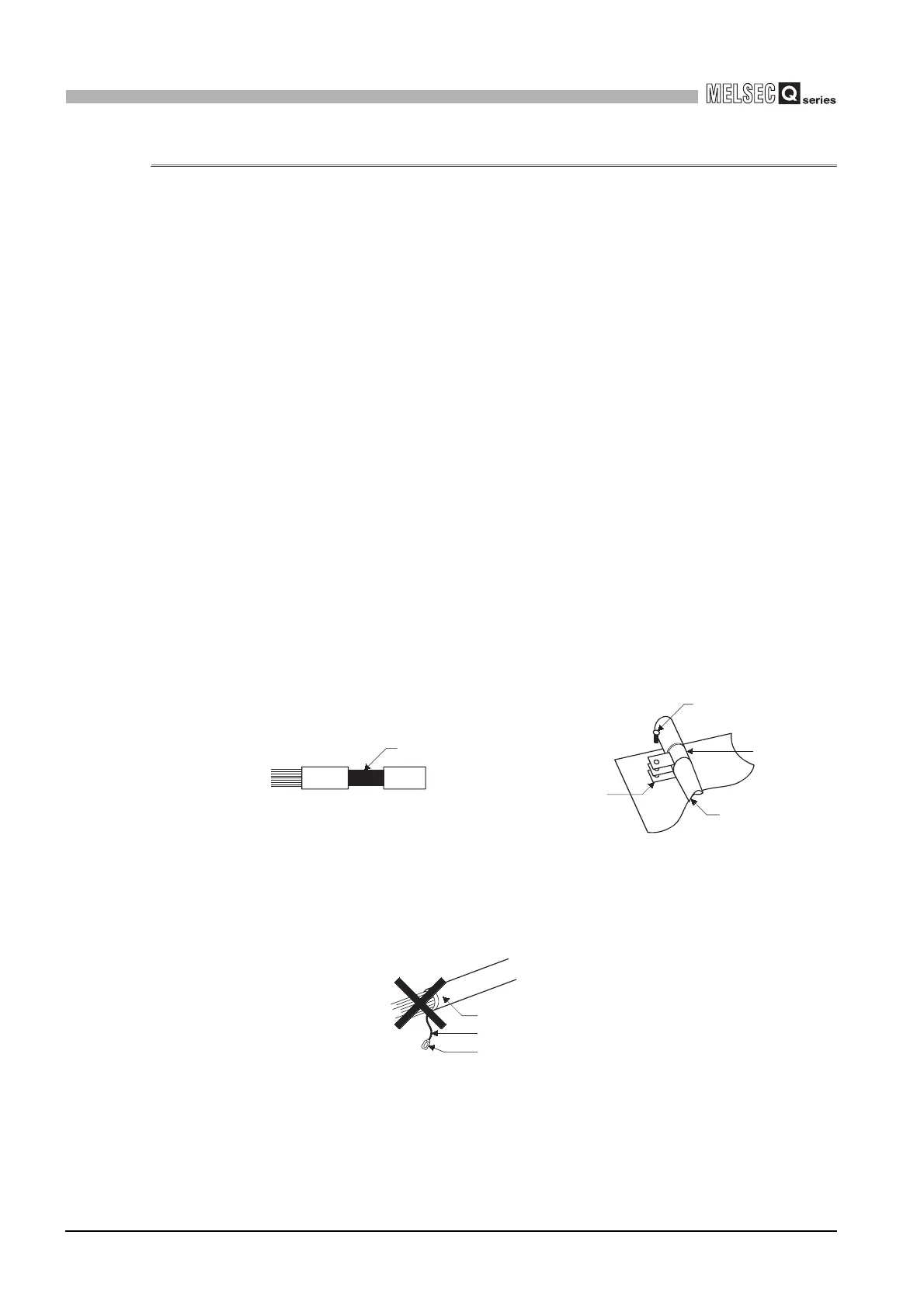
(1) Grounding of shielded of shield cable
• Ground the shield of the shielded cable as near the module as possible taking
care so that the grounded cables are not induced electromagnetically by the
cable to be earthed.
• Take an appropriate measures so that the shield section of the shielded cable
from which the outer cover was partly removed for exposure is earthed to the
control panel on an increased contact surface.
A clamp may also be used as shown in Diagram 9.2.
In this case, however, apply a cover to the painted inner wall surface of the
control panel which comes in contact with the clamp.
Note) The method of grounding by soldering a wire onto the shield section of the
shielded cable as shown in Diagram 9.3 is not recommended. The high
frequency impedance will increase and the shield will be ineffective.
Diagram 9.1 Part to be exposed Diagram 9.2 Shield grounding (Correct example)
Diagram 9.3 Shield grounding (Incorrect example)
Shield section
Screw
Clamp fitting
Shield cable
Paint mask
Shield cable
Wire
Solderless terminal, crimp contact
 Loading...