9 - 8
9.1 Requirements for Conformance to EMC Directive
9.1.4 Power Supply Module and Q00JCPU's Power Supply Part
9
EMC AND LOW VOLTAGE DIRECTIVES
9.1.4 Power Supply Module and Q00JCPU's Power Supply Part
Always ground the LG and FG terminals after short-circuiting them.
9.1.5 When Using MELSEC-A Series Modules
The following describes the case where the MELSEC-A series module is used, using the
QA1S6 B, QA6 B, and QA6ADP+A5 B/A6 B as the extension base unit.
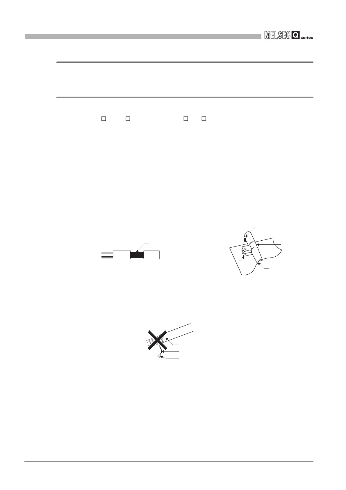
(1) Cable
(a) Grounding of the shield of the shielded cable
• Ground the shield of the shielded cable as near the unit as possible taking
care so that the grounded cables are not induced electromagnetically by the
cable to be earthed.
• Ground the shield of the shielded cable, which was exposed by removing a
part of the outer sheath, to the control panel as a large area as possible.
A clamp may also be used as shown in Diagram 9.12.
However, mask the part inside the control panel, with which the clamp comes
in contact, when coating.
Note) The method of grounding by soldering a wire onto the shield section of the
shielded cable as shown in Diagram 9.13 is not recommended. The high
frequency impedance will increase and the shield will be ineffective.
Diagram 9.11 Part to be exposed Diagram 9.12 Shield grounding (Correct example)
Diagram 9.13 Shield grounding (Incorrect example)
Shield section
Screw
Clamp fitting
Shield cable
Paint mask
Shield cable
Wire
Solderless terminal, crimp contact
 Loading...