12 - 14
12.2 Troubleshooting
12.2.7 Flowchart for when the "RUN" LED turned off
12
TROUBLESHOOTING
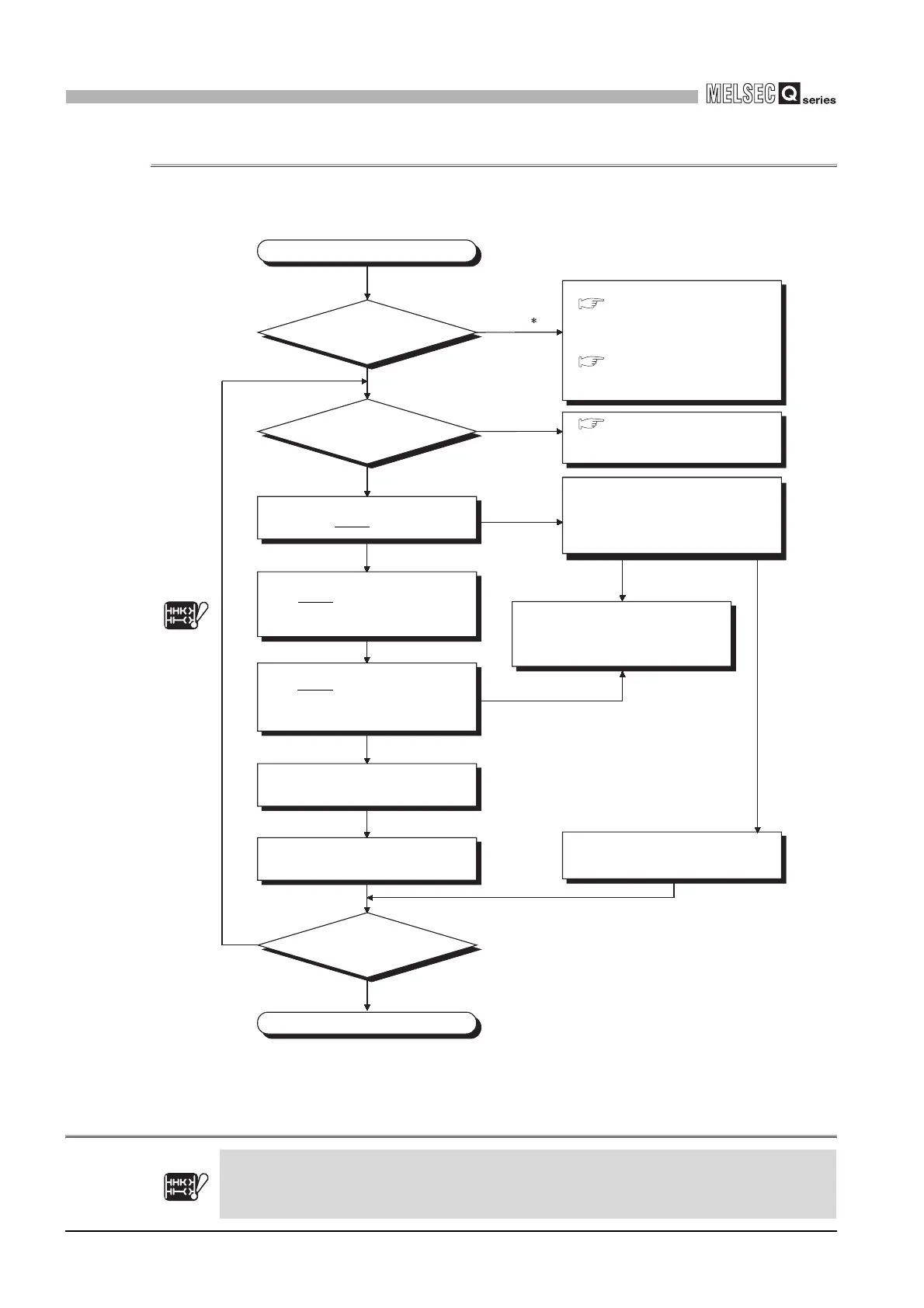
12.2.7 Flowchart for when the "RUN" LED turned off
The following shows the flowchart for when the "RUN" LED of
the CPU module turns off during operation of the programmable controller.Note7
* : This applies to the redundant power supply module.
Diagram 12.7 Flowchart for when the "RUN" LED is turned off
Note7
Basic
Note12.7
YES
NO
YES
NO
Completed
Can "RUN" LED turn on?
How is the
"POWER" LED of the power
supply module?
Is "ERR." LED
on/flickering?
"RUN" LED is off.
"RUN" LED is
on.
Off or
On (red)
Turned on green
"RUN" LED does
not turn on.
For the case of (1) For the
case of (2)
"RUN" LED is on.
Set the CPU module's RUN/STOP
switch to STOP and write END
to address 0 with the GX Developer.
(1)
Excessive noise generation(2)
Set the CPU module's RUN/STOP
switch to RUN and enter to
the monitor mode with the GX
Developer to be operated.
Possible cause is a sequence
program error.
Check the program and modify the
program error location.
Reset the CPU module RESET/L.
CLR switch.
Please consult your local Mitsubishi
service center or representative,
explaining a detailed description of
the problem.
(When off)
Section 12.2.5 "Flowchart for
when the "POWER" LED has
turned off."
(When on (red))
Section 12.2.6 Flowchart for
when the "POWER" LED has
turned on (red)
Section 12.2.9 "Flowchart for
when the "ERR." LED is
on/flickering."
Connect a surge suppression
circuit, such as CR, to the noise
source.
The "RUN" LED has turned off.
Programmable controller part
fault/poor connection between
the module and base unit
Section 12.2.5
Note12.7
Section 12.2.6
Section 12.2.9
Note12.7
Note12.7
In the case of the Basic model QCPU, use the "RUN/STOP/RESET switch" for operation.
Basic
Note12.7
 Loading...