15 - 3
15. HARDWARE SPECIFICATIONS OF CPU MODULES
(5) BOOT LED
ON:
OFF:
Execution of the boot operation is completed.
No boot operation has been executed.
(6) RUN/STOP key switch
(7)
LED display
(Q3A, Q4ACPU only)
Can display up to 16 characters.
Displays comments for errors detected in self-diagnosis, comments by LED display instructions, clock data by SET
SM212, or annunciator F number comments by SET F instructions.
(8)
Display reset switch (Q3A,
Q4ACPU only)
Switch used to clear the current LED display. The next data is displayed, if any.
(9) Battery (A6BAT) Backup battery for the built-in RAM and the power failure compensation function.
(10) Battery connector pin
Used for connection of the battery lead wire.
(To prevent battery drain, the battery lead wire is disconnected from the connector before shipment. See Section
18.6.)
(11) Memory card EJECT button Used to eject the memory card from the CPU module. (Refer to Section 18.7)
(12)
Memory card installing
connector
Connector for installing the memory card in the CPU module.
(13)
Memory card in/out switch
(with built-in LED)
Used to enable/disable memory card installation or removal while the power is ON. Factory-set to OFF .
Refer to Section 15.3 (3) and (4) for installation or removal of a memory card.
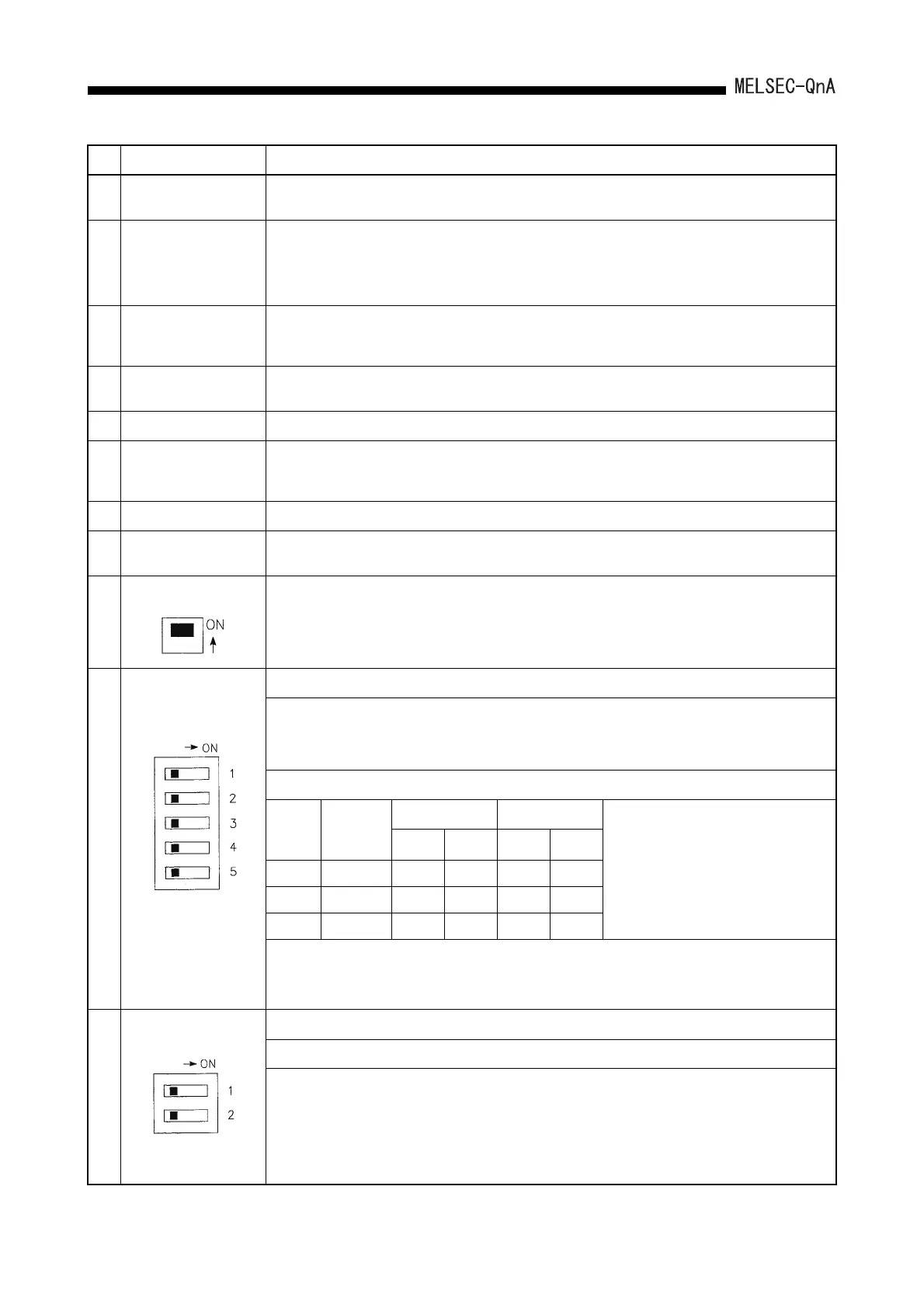
(14)
System setting switch 1
Settings required to operate the CPU module are made. All switches are set to OFF before shipment.
SW2 to 4: Parameter area Setting of the memory in which parameters are written.
System
setting
switch 1
Built-in RAM
Memory Card A Memory Card B
*SW2 to 4 are valid even if SW1 is OFF.
RAM ROM RAM ROM
SW2 OFF ON OFF ON OFF
SW3 OFF OFF ON ON OFF
SW4 OFF OFF OFF OFF ON
(15)
System setting switch 2
Settings required to operate the CPU module are made. All switches are set to OFF before shipping.
SW1: Not used. (Fixed to OFF.)
No. Name Application
RUN/STOP:Starts/stops sequence program operation.
L.CLR: Clears all data in the latch area (to "OFF" or "0") which is set with parameters.
Clears sampling trace and status latch registrations.
RESET: Resets the hardware. Resets and initializes operation when an operation error occurred.
ON: Cannot be removed (LED lit)
OFF: Can be removed (LED unlit)
:
oot sett
ng
ett
ng o
t
e memory use
or operat
on.
ON: Boot operation
OFF: Boot operation is not performed.
W5:
ystem protect Prohibition o
all writing and control directions to the
PU module.
ON: System protection enabled
OFF: System protection disabled
SW2: Peripheral protocol. Select the type of the peripheral device connected to the peripheral interface of the
CPU module.
(When accessing an ACPU on another station from a peripheral device for ACPU, set this switch to "ON".
The setting becomes valid immediately after switching.)
ON: Peripheral device for ACPU
OFF: Peripheral device for QnACPU
 Loading...

