6881076C25-E September 5, 2008
Theory of Operation: ASTRO Spectra Plus VOCON Board 3-41
3.4.4 ASTRO Spectra Plus RX Signal Path
The vocoder processes all received signals digitally. This requires a unique back end from a
standard analog radio. This unique functionality is provided by the ABACUS IC with the KRSIC
(U200) acting as the interface to the DSP. The ABACUS IC located on the transceiver board
provides a digital back-end for the receiver section. It provides a digital output of I (In phase) and Q
(Quadrature) data words at a 20 kHz sampling rate (refer to the Receiver Back-End section for more
details on ABACUS operation). This data is passed to the DSP through an interface with the KRSIC
(U200) for appropriate processing. The KRSIC interface to the ABACUS is comprised of the four
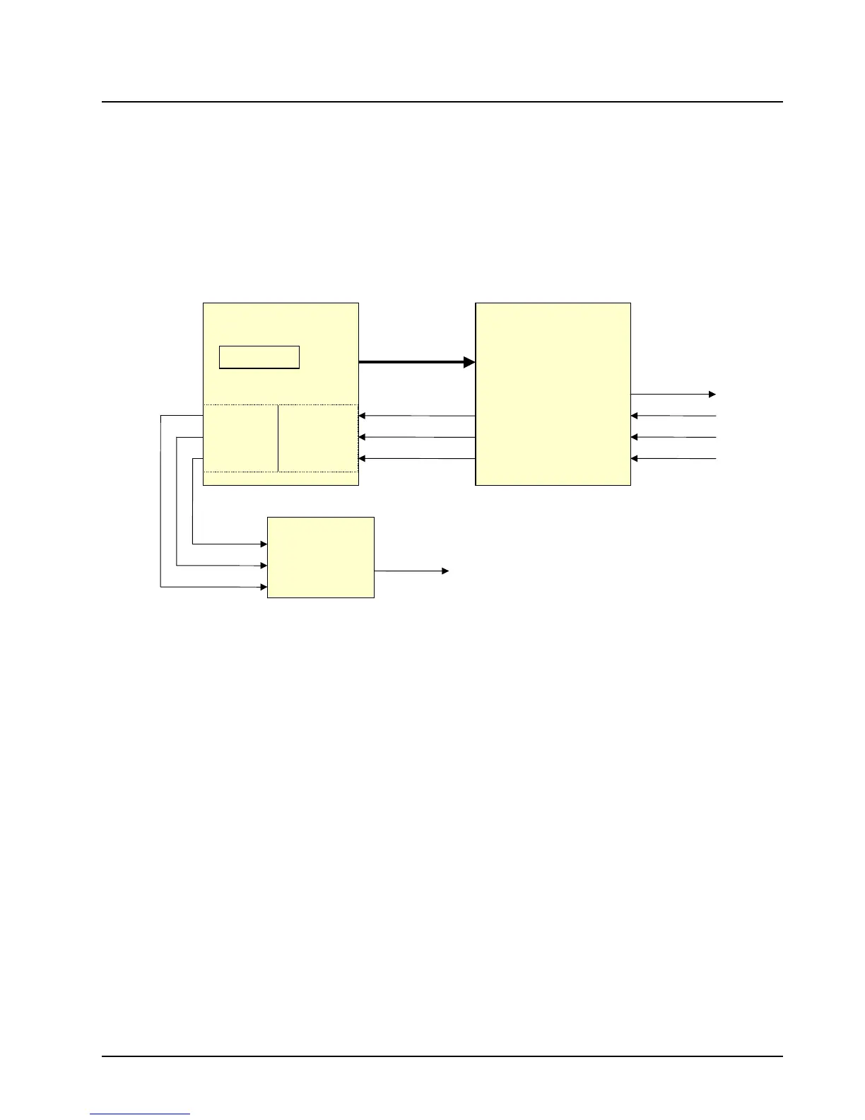
signals SBI, DIN, DIN*, and ODC (refer to Figure 3-16).
Figure 3-16. ASTRO Spectra Plus RX Signal Path
NOTE: An asterisk symbol (*) next to a signal name indicates a negative or NOT logic true signal.
ODC is a clock ABACUS provides to the KRSIC. Most internal KRSIC functions are clocked by this
ODC signal at a rate of 2.4 MHz and is available as soon as power is supplied to the circuitry. This
signal may initially be 2.4 or 4.8 MHz after power-up. It is programmed by the KRSIC through the SBI
signal to 2.4 MHz when the KRSIC is initialized by the MCU (in the Patriot IC) through GPIO. SBI is
a programming data line for the ABACUS. This line is used to configure the operation of the
ABACUS and is driven by the KRSIC. The MCU programs many of the KRSIC operational features
through the GPIO interface. When the KRSIC is programmed properly by the MCU, the KRSIC in
turn sends this data to the ABACUS through the SBI.
DIN and DIN* are the data lines on which the I and Q data words are transferred from the ABACUS.
These signals make up a differentially encoded current loop. Instead of sending TTL type voltage
signals, the data is transferred by flowing current one way or the other through the loop. This helps to
reduce internally generated spurious emissions on the RF board. There are single-ended driver
circuits between the ABACUS and the KRSIC, which are used to convert the differential current
driven by the ABACUS. After the driver circuits, the I and Q samples are detected and transferred to
a serial transmitter.
SDO
PATRIOT
U300
DSP 56600
KRSIC
U200
ABACUS II
Interface
SBI
ODC
Data In*
Data In
J501-1
J501-7
J501-2
J501-6RXSBI
RXODC
RXData
HI
RXData
LO
ABA_FSYNC
ABA_CLK
ABA_RXD
Serial Receive Data
20 kHz
800 KHz
SC0B
SRDB
SC1B
D0-D7,
RS0-RS4
GPIO
CODEC
U402
FSR
MCLK
DR
Command
Board
J501-40
SC2A
SCKA
STDA
SAP BBP
RO_NEG
8 kHz
512 kHz
Data
 Loading...


