Chapter 5 Troubleshooting Charts
5.1 Introduction
This chapter contains detailed troubleshooting flowcharts. These charts should be used as a guide in
determining the problem areas. They are not a substitute for knowledge of circuit operation and
astute troubleshooting techniques. It is advisable to refer to the related detailed circuit descriptions in
the theory section prior to troubleshooting a radio.
5.2 List of Troubleshooting Charts
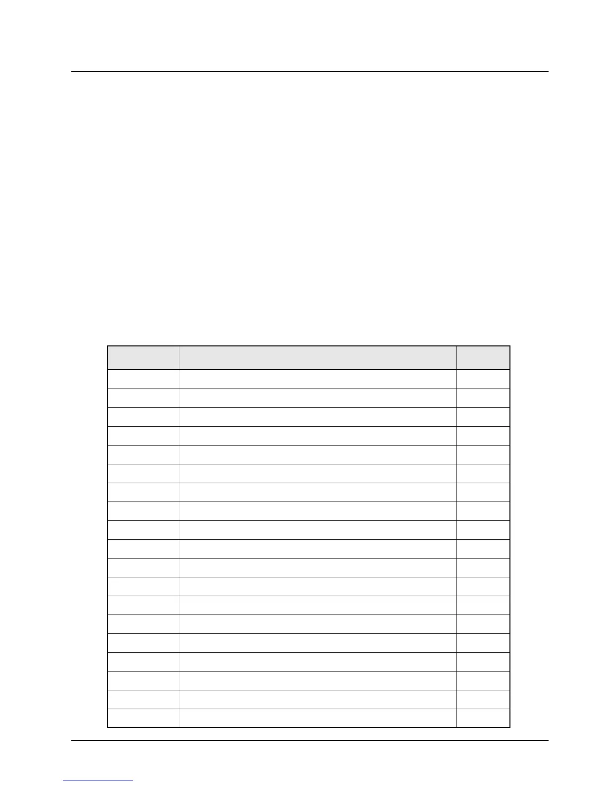
Most troubleshooting charts (see Table 5-1) end up by pointing to an IC to replace. It is not always
noted, but is good practice, to verify supplies and grounds to the affected IC, and trace
continuity to the malfunctioning signal and related circuitry before replacing any IC. For
instance, if a clock signal is not available at a destination IC, continuity from the source IC should be
checked before replacing the source IC.
Table 5-1. List of Troubleshooting Charts
Chart
Description
Page
Chart C.1 RF Board Back-End 5-3
Chart C.2 Command Board 5-4
Chart C.3 Radio Power-Up Fail 5-5
Chart C.4 Bootstrap Fail 5-6
Chart C.5 01/90, General Hardware Failure 5-7
Chart C.6 01/81, Host ROM Checksum Failure 5-7
Chart C.7 01/82, or 002, External EEPROM Checksum Failure 5-8
Chart C.8 01/84, SLIC Initialization Failure 5-8
Chart C.9 01/88, MCU (Host μC) External SRAM Failure 5-9
Chart C.10 01/92, Internal EEPROM Checksum Failure 5-9
Chart C.11 02/A0, ADSIC Checksum Failure 5-10
Chart C.12 02/81, DSP ROM Checksum Failure 5-10
Chart C.13 02/88, DSP External SRAM Failure U414 5-11
Chart C.14 02/84, DSP External SRAM Failure U403 5-11
Chart C.15 02/82, DSP External SRAM Failure U402 5-12
Chart C.16 02/90, General DSP Hardware Failure 5-12
Chart C.17 09/10, Secure Hardware Failure 5-13
Chart C.18 09/90, Secure Hardware Failure 5-13
Chart C.19 No RX Audio 5-14
 Loading...


