6881076C25-E September 5, 2008
Theory of Operation: Command Board 3-11
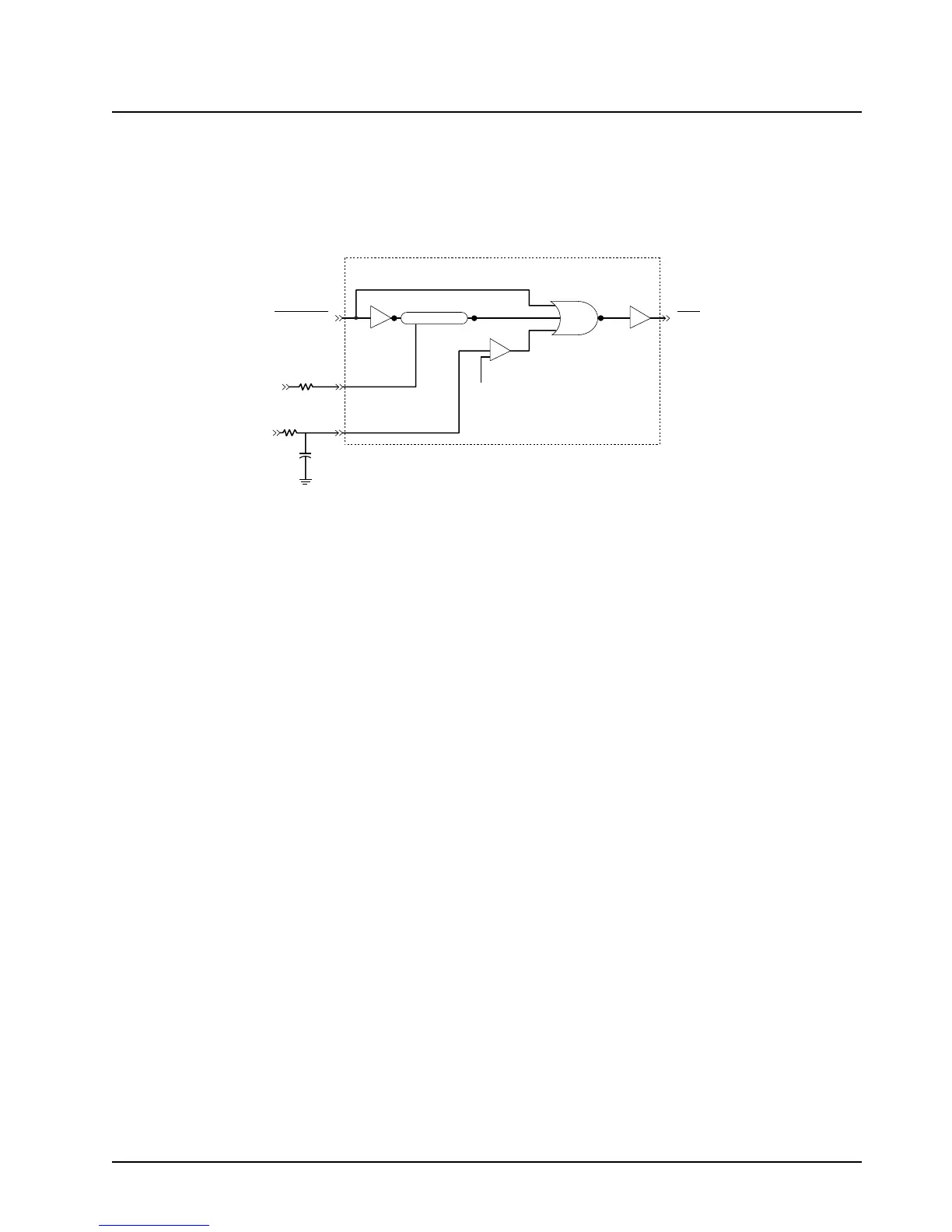
The three inputs to the NOR gate (SW9.6-V, RPCIC EN, and RPCIC_EN delayed) must be at a logic
low to enable the power-on reset (POR*) to a high logic state. During this power-up sequence, this
reset is delayed approximately 170 ms after the B+ voltage is sensed. This delay is needed to allow
the supply voltages and oscillators to stabilize before releasing the VOCON board’s microprocessor.
Figure 3-5 illustrates the internal function of the POR* within the SIOIC device.
Figure 3-5. Power-on Reset
3.2.6 Serial Communications on the External Bus
Serial communications on the external bus use the BUS+ (J502-25), BUS- (J502-22), and BUSY
(J502-9) lines.
These three lines are bidirectional; therefore, numerous devices can be in parallel on the bus. All
devices monitor the bus while data is being transmitted at a 9600-baud rate. The transmitted data
includes the address of the device for which the data is intended. Examples of the different types of
data are: control head display data and button closure data.
Data bus drivers for the BUS+ and BUS- lines are differentially driven, having BUS- inverted from the
state of BUS+. The idle states are: BUS+, a logic high; and BUS-, a logic low. The drivers are so
designed that any of the devices on the bus can drive these lines to their non-idle state without
loading problems.
In a typical transmission, the microcontroller examines the BUSY line. If the BUSY line is in the idle
state, the microcontroller sets the BUSY line and then transmits. At the end of transmission, the
microcontroller returns the BUSY line to idle. The microcontroller sets the BUSY line via
microcontroller pin 30, SIOIC pins 10 and 13, and J502-9.
Data transmission is sent onto the bus asynchronously. When the microcontroller sends data onto
the bus, the microcontroller also monitors the transmitted data as a collision detection measure. If a
collision is detected as a result of receiving a different data pattern, the microcontroller will stop
transmission and try again. The microcontroller monitors and receives data via the BUS+ line
(J502-25) to the SIOIC (U522, pin 17) and the BUS- line (J502-22) to the SIOIC (U522, pins 18 and
20), and pin 20 of the microcontroller. Data is transmitted from microcontroller pin 19 to the SIOIC to
BUS+ (J501, pin 25), and the SIOIC to BUS- (J501, pin 22).
In the remote version of the radio, option cards can be installed. If data transmission is required, data
is transmitted from J502-20 to SIOIC pin 19, then from the SIOIC to BUS+ (J501, pin 25), and the
SIOIC to BUS- (J501, pin 22).
SIOIC
(Internal)
15
25
14
C511
NSW+5V
SW9.6V
5.6V Reference
P501-27
POR
R524
R526
RPCIC EN
 Loading...


