6881076C25-E September 5, 2008
Troubleshooting Procedures: Power Amplifier Procedures 4-43
4. Power Zero and Current Greater Than 5 A.
- Check harmonic filter, antenna switch, and matching circuits beyond final stage.
5. Power Zero and Current Between 2 and 5 A.
- Check driver and/or final stages.
6. Power Zero and Current Less Than 1 A.
- Check LLA/driver circuitry.
4.5.1.3.4 Isolating Failures
Methods of analyzing individual stages of the power amplifiers are detailed below. Most of the stages
are Class C and must be analyzed under relatively high RF power levels. Generators capable of
such levels may not be available in all service shops, therefore the tests below are arranged in order
of ascending power. This tends to allow the preceding stage to be the source of RF power for testing
the next stage.
Testing Low-Level Amplifier (LLA) Circuitry
The required DC and RF conditions are defined in Table 4-15 on page 4-40. Measure LLA voltages
according to Table 4-16.
If the above DC bias conditions are correct, check to see if the LLA is providing drive power to the
driver Q3804. Do so by checking Q3804's collector current under normal drive conditions, as follows:
• Remove R3810 and L3806 (Be sure to reinstall after testing).
• Solder wires to the remaining pads.
• Place an ammeter in series with the collector of Q3804.
• Check for 0.1 to 0.5 A. depending on the control voltage.
NOTE: With no RF drive to the input of the PA, the collector current of Q3804 should be zero.
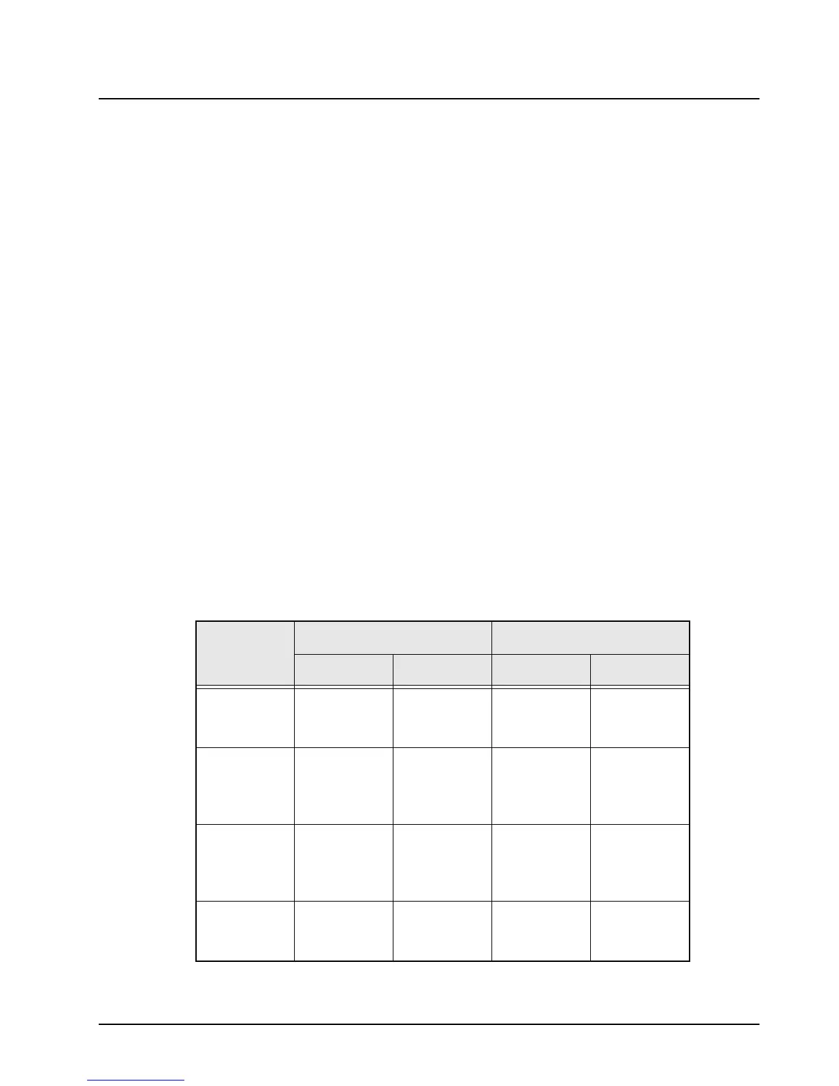
Table 4-16. LLA and Pre-Driver Typical Voltages
CONTROL
VOLTAGE
RF DRIVE OFF RF DRIVE ON
9.2 V 6.0 V 9.2 V 6.0 V
Q3801
Base
Collector
–
0.7
8.3
–
0.7
9.0
–
0.7
8.0
–
0.5
8.8
Q3802
Base
Collector
Emitter
–
7.7
2.0
8.3
–
8.4
1.4
9.0
–
7.5
2.3
8.0
–
8.2
1.2
8.8
Q3806
Base
Collector
Emitter
–
5.1
7.7
4.5
–
4.1
8.4
3.4
–
5.1
7.5
4.5
–
4.1
8.2
3.4
Q3804
Base
Collector
–
0.5
13.8
–
0.5
13.8
–
0.0
13.3
–
0.2
13.4
 Loading...


